background image

92

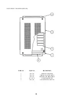
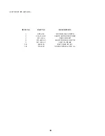
ASSY DRIVE BD (SRT-4300)

ITEM NO.

PART NO.

DESCRIPTION

1

SRT-4301

WOODEN BASE DRIVE

2

838-12912-91

SERVO MOTOR DRIVE BD

3

838-13366

DRIVE BD SRT

4

839-0451-01

LIGHT CONTROL BD TTR

5

839-1011-01

SSR 1EA BD BR

101

400-5454

RECTIFIER DC 45V

102

270-5020

NOISE FILTER AC250V 6A

Содержание Rally 2 DX

Страница 1: ...USER MANUAL 1998 SEGA Sega Rally 2 DX ...

Страница 2: ...AKE S 10 1 ADJUSTING AND REPLACING THE VR 10 2 GREASING 10 3 GREASING TO THE HAND BRAKE 10 4 REPLACING THE HAND BRAKE MICROSWITCH 11 MAINTENANCE OF MECHANISM UNIT 11 1 ADJUSTMENT AND REPLACEMENT OF VOLUME 11 2 GREASING 11 3 REPLACING THE SAFETY RUBBER 12 COIN SELECTOR 13 PROJECTOR 13 1 CLEANING THE SCREEN 13 2 MITSUBISHI PROJECTOR 13 3 TOSHIBA PROJECTOR 14 REPLACEMENT OF FLUORESCENT LAMP 14 1 REPL...

Страница 3: ...1st PRINTING MAR 98 MANUAL NO 4200 6374 02 OWNER S MANUAL OWNER S MANUAL OWNER S MANUAL OWNER S MANUAL OWNER S MANUAL SEGA ENTERPRISES USA DLX VERSION ...

Страница 4: ...event a warranted part described above fails shall be at its option to replace or repair the defective part during the warranty period For Warranty claims contact your Sega Distributor Should the Seller determine by inspection that the product was caused by Accident Misuse Ne glect Alteration Improper Repair Installation or Testing the warranty offered will be null and void Under no circumstances ...

Страница 5: ...2 DLX a new SEGA product This manual is intended for those who have knowledge of electricity and technical expertise espe cially in ICs CRTs microprocessors and circuit boards Read this manual carefully to acquire sufficient knowledge before working on the machine Should there be a malfunction non technical personnel should under no circumstances touch the interior system Should the need arise con...

Страница 6: ...your obsolete outlet Do not defeat the safety purpose of the grounding type plug Power Cord Protection Power supply cords should be routed so that they are not likely to be walked on or pinched by items placed upon or against them paying particular attention to cords at plugs convenience receptacles and the point where they exit from the product Overloading Do not overload wall outlets extension c...

Страница 7: ...heating units or hot air In the vicinity of highly inflammable volatile chemicals or hazardous matter On sloped surfaces In the vicinity of emergency response facilities such as fire exits and fire extinguishers Places subject to any type of violent impact Dusty places INSTALLATION PRECAUTIONS Verify the amperage of the branch circuit outlet before plugging in the power plug Do not over load the c...

Страница 8: ...mage do not put the following items on or in the periphery of the product Flower vases flower pots cups water tanks cosmetics and receptacles containers vessels containing chemicals and water 1 PRECAUTIONS TO BE HEEDED FOR OPERATION PRECAUTIONS TO BE HEEDED FOR OPERATION BEFORE STARTING THE OPERATION In order to prevent accidents be sure to comply with the following points before and during operat...

Страница 9: ...y to cause a potentially hazardous situation To avoid electric shock and short circuit do not allow customers to put hands and fingers or extraneous matter in openings of the product or small openings in or around doors To avoid electric shock and short circuit do not allow the customers to unplug the power plug without a justifiable reason Although this product has the accident preventive coverin...

Страница 10: ...WIDTH LENGTH HEIGHT WEIGHT Weight DURING SHIPPING 1183 LBS 433 LBS 49 LBS 1250 LBS All measurements are in inches 42 X 23 X 22 5 44 5 X 31 X 70 53 X 81 X 57 53 X 114 X 92 701 LBS PTV AC UNIT MARQUEE REAR CABI CASH BOX COIN CHUTE DOOR FRONT CABINET REAR CABINET MARQUEE ...

Страница 11: ...7 3 ACCESSORIES ...

Страница 12: ...MODEL 3 GAME BOARDS NEVER SHIP MODEL 3 GAME BOARDS OUTSIDE OF CAGE OUTSIDE OF CAGE THE SHIPMENT METHOD DESCRIBED BELOW ONLY APPLIES TO MODEL 3 BOARDS CONTAINED IN THE FOLLOWING GAMES NO OTHER GAMES BOARDS ARE TO BE SHIPPED IN THE CAGE AS THEY MAY BE DAMAGED BEYOND REPAIR PLEASE SHIP THEM WITHOUT CAGE PROPERLY PROTECTED DURING SHIPPING LOST WORLD VIRTUA FIGHTER 3 SUPER GT SEGA BASS FISHING STRIKER ...

Страница 13: ...THE FRONT CABINET JOINING OF CABINETS SECURING IN PLACE ADJUSTER ADJUSTMENT POWER SUPPLY ASSEMBLING CHECK Assembling should be performed as per this manual Since this is a complex machine erroneous assembling may cause damage to the machine or malfunctioning to occur When assembling be sure to perform work by plural persons Depending on the assembly work there are some cases in which performing th...

Страница 14: ... and install the Wire Cover 2 3 Installing the Billboard by one person is difficult Be sure to use plural persons to perform work safely and accurately To perform work safely and securely be sure to prepare a step which is in a secure and stable condition Performing work without using a step can caus e a violent falling down accident 1 ASSY OF FRONT CABI ...

Страница 15: ...ppropriate position Insert the Rear Cabinet s Joint Bracket L R into the Front Cabinet s square holes and secure with 4 hexagon bolts for each Due to its large size it is very difficult for one person alone to install the billboard Make sure 2 or more persons are available to perform this work Attempting to perform the installation alone can cause an accident 1 2 ...

Страница 16: ...t upward and secure the height of the leg adjuster This machine has 8 each of casters and adjusters shown below When the installation position is determined cause the adjusters to come into contact with the floor directly make adjustments in a manner so that the casters will be raised approximately 5mm from the floor and make sure that the machine position is level Be sure to have all the Adjuster...

Страница 17: ...urn the machine s power supply Simultaneously with turning power on the machine starts intialization setting movements and displays the intialiazation setting movement mode on the screen Do not touch the machine until the intialization setting movements are automatically finished When the power is turned ON the Billboard s fluorescent lamp lights up the steering wheel turns right and left and then...

Страница 18: ...board memory to be tested automatically The game board is satisfactory if the display beside each IC No shows GOOD ASSEMBLING CHECK 5 The TEST MENU allows for each part of the cabinet to be checked the Monitor to be adjusted and the coin and game related various functions to be performed MEMORY TEST IC GOOD IC GOOD IC GOOD IC GOOD IC GOOD IC GOOD IC GOOD IC GOOD IC GOOD IC GOOD IC GOOD IC GOOD IC ...

Страница 19: ...2345678 1234567890123456789012345678 1234567890123456789012345678 1234567890123456789012345678 1234567890123456789012345678 1234567890123456789012345678 1234567890123456789012345678 1234567890123456789012345678 1234567890123456789012345678 1234567890123456789012345678 1234567890123456789012345678 1234567890123456789012345678 1234567890123456789012345678 1234567890123456789012345678 123456789012345...

Страница 20: ...n pay careful attention so that Casters do not tread power cords Damaging the power cords can cause an electric shock and or short circuit When lifting the cabinet be sure to hold the catch portions or bottom part Lifting the cabinet by holding other portions can damage parts and installation portions due to the empty weight of the cabinet and cause personal injury Use care when handling glass mad...

Страница 21: ...e lower right hand side Pull the Lever to adjust the seat position Insert a coin s Insert one play worth of coins to have the Select Mode appear Up to 9 credits can be counted at a time Coins inserted after counting 9 will not be counted or rejected Credits will not be displayed after Select Mode When a coin is inserted in one of the linked seats the monitor s of the other seat s will be in the en...

Страница 22: ...ose the desired car by turning the Steering Wheel and confirm with the Accelerator Pedal TRANSMISSION SELECT mode appears Turn the Steering Wheel and select either AT AUTO MATIC or MT MANUAL 4 SHIFTS and confirm with pedal The NAME ENTRY MODE appears Turn the Steering Wheel to choose input characters and confirm with pedal After inputing the 3 charac ters game starts WHEN PLAYING IN TH ECHAMPIONSH...

Страница 23: ...rt time decreases Passing a mid course checkpoint increases time and game continues Failing to pass the checkpoint within the time limit causes game over Finishing the GOAL in each stage will let you proceed to the next stage In the Championship mode you proceed starting from DESERT novice sequentially to MOUNTAIN intermedi ate SNOWY expert with one lap for each and RIVIERA expert with 2 laps Fini...

Страница 24: ... majority The Car Select Mode appears Select from among the 6 types Depending on the type of car your operating sensation may somewhat vary Select the desired car with the Steering Wheel Step on the Accelerator to confirm The Transmission Select Mode appears Turn the Steering Wheel to choose either of AT AUTOMATIC or MT MANUAL 4 SHIFTS and confirm with the Accelerator Pedal 1 2 3 ...

Страница 25: ...ed the lower left portion shows tachometer and shift speed the lower right hand portion indicates the selected car and the driver s name entered After game start time decreases Passing a mid course checkpoint increases time and game continues Failing to pass the checkpoint within the time limit causes game over Finishing the GOAL in each stage will let you proceed to the next stage In the Champion...

Страница 26: ...S When you enter the test mode the Handlebar and Bike Body are unlocked Do not lean against the BikeBody when you press the test button Failure to observe this can cause violent falling down accidents as the Bike Body will bank When you finish the test mode the handlebar and Bike Body will be locked In the case where plural machines are linked for communication play if even one seat enters the tes...

Страница 27: ...rt circuit Adjust to the optimum sound volume by considering the environmental requirements of the installation location If the COIN METER and the game board are electrically disconnected game play is not possible SOUND VOLUME Controls the speaker volume TEST BUTTON TEST SW For the handling of the TEST BUTTON refer to the section on test mode SERVICE BUTTON SERVICE SW Gives credits without registe...

Страница 28: ...his will select the item s test After the test is complete move the mark to EXIT and press the TEST BUTTON to return to game mode 3 1 2 TEST MENU MEMORY TEST STEERING REACTION TEST COCKPIT REACTION TEST INPUT TEST OUTPUT TEST SOUND TEST C R T TEST GAME ASSIGNMENTS COIN ASSIGNMENTS BOOKKEEPING BACKUP DATA CLEAR EXIT SELECT WITH SERVICE BUTTON AND PRESS TEST BUTTON The Following FIGURES TABLES show ...

Страница 29: ...and press the Test Button to enter the selected item CENTERING Press the Test Button or the Start Button to apply automatic centering to Steering Wheel RIGHT The Steering Wheel turns up to the RIGHT maximum value LEFT The Steering Wheel turns up to the LEFT maximum value FORCE Adjusts the Steering Wheel s reaction force 0 15 minimum 15 15 maximum This on screen adjustment will be effective whent h...

Страница 30: ...cates which shift and SHIFT LEVER is in N means neutral INPUT TEST STEERING WHEEL H GAS PEDAL H BRAKE PEDAL H SHIFT UP OFF SHIFT DOWN OFF VIEW 1 ZOOM IN OFF VIEW 2 ZOOM OUT OFF START OFF HAND BRAKE OFF GEAR POSITION N COIN CHUTE 1 OFF COIN CHUTE 2 SERVICE SW OFF TEST SW OFF PRESS TEST BUTTON TO EXIT Choose OUTPUT TEST to cause the following lower screen to appear In this test check the status of e...

Страница 31: ...456789012345678 1234567890123456789012345678 1234567890123456789012345678 1234567890123456789012345678 1234567890123456789012345678 1234567890123456789012345678 1234567890123456789012345678 1234567890123456789012345678 1234567890123456789012345678 1234567890123456789012345678 1234567890123456789012345678 1234567890123456789012345678 1234567890123456789012345678 Select C R T TEST to cause the MONIT...

Страница 32: ... settings These FIGURES TABLES show the factory recommended settings These FIGURES TABLES show the factory recommended settings GAME DIFFICULTY Sets the Game Difficulty in 5 catagories from 1 to 8 The greater the number is the higher the difficulty level becomes Alternately it may display each catagory by name Very Easy Easy Normal Hard Very Hard CABINET TYPE Set to DELUXE or STANDARD as applicabl...

Страница 33: ... game 1 5 credits are selected COIN CREDIT SETTING Sets the CREDITS increase increment per coin insertion There are 27 setings from 1 to 27 expressed in XX CREDIT as against XX COINS inserted TABLE 7 11a 7 11b 27 refers to FREE PLAY When the COIN CHUTE TYPE is set to INDIVIDUAL there are some setting numbers not displayed as indicated in TABLE 7 11b MANUAL SETTING This allows credit increase setti...

Страница 34: ...OINS 1 CREDIT SETTING 13 1 COIN 1 CREDIT SETTING 14 1 COIN 2 CREDITS SETTING 15 1 COIN 1 CREDIT 2 COINS 3 CREDITS SETTING 16 1 COIN 3 CREDITS SETTING 17 3 COINS 1 CREDIT SETTING 18 4 COINS 1 CREDIT SETTING 19 1 COIN 1 CREDIT 2 COINS 2 CREDITS 3 COINS 3 CREDITS 4 COINS 5 CREDITS SETTING 20 1 COIN 5 CREDITS SETTING 21 5 COINS 1 CREDIT SETTING 22 1 COIN 2 CREDITS SETTING 23 2 COINS 1 CREDIT 4 COINS 2...

Страница 35: ...IN TO CREDIT 1 COIN 1 CREDIT 2 COINS 1 CREDIT 3 COINS 1 CREDIT 4 COINS 1 CREDIT 5 COINS 1 CREDIT 6 COINS 1 CREDIT 7 COINS 1 CREDIT 8 COINS 1 CREDIT 9 COINS 1 CREDIT COIN CHUTE MULTIPLIER 1 COIN COUNTS AS 1 COIN 1 COIN COUNTS AS 2 COINS 1 COIN COUNTS AS 3 COINS 1 COIN COUNTS AS 4 COINS 1 COIN COUNTS AS 5 COINS 1 COIN COUNTS AS 6 COINS 1 COIN COUNTS AS 7 COINS 1 COIN COUNTS AS 8 COINS 1 COIN COUNTS ...

Страница 36: ...atus up to the present are shown on 2 pages Press the TEST BUTTON to proceed to PAGE 2 2 BOOKKEEPING PAGE1 2 COIN CHUTE 1 XXXXXXXXXXX COIN CHUTE 2 XXXXXXXXXXX TOTAL COINS XXXXXXXXXXX COIN CREDITS XXXXXXXXXXX SERVICE CREDITS XXXXXXXXXXX TOTAL CREDITS XXXXXXXXXXX NUMBER OF GAMES XXXXXXXXXXX TOTAL TIME XDXXHXXMXXS PLAY TIME XDXXHXXMXXS AVERAGE PLAY TIME XXMXXS LONGEST PLAY TIME XXMXXS SHORTEST PLAY T...

Страница 37: ...ustments or VR replacement is needed Also be sure to apply grease to the VR gear portion once every 3 months 8 1 REMOVING THE CONTROL PANEL Insert the test mode have the V R value displayed onthe screen Remove the 11 screws from the right hand side panel Cover as shown Loosen the 2 screws which secure the Volume Bracket and you can move the Volume Bracket Moving the Volume Bracket disengages gear ...

Страница 38: ...ensure that Volum Value display is within the range of 80 2H when the handle is in the cenetering position 3 4 5 8 2 REPLACING AND ADJUSTING THE HANDLE S VR Never touch places other than those specified Touching places not specified can cause electric shock and or short circuit After the replacement or adjustment of the VR be sure to set the variable value of the VR in the test mode s Volume Setti...

Страница 39: ...fied can cause electric shock and or short circuit After the replacement or adjustment of the VR be sure to set the variable value of the VR in the test mode s Volume Setting Apply greasing to the Volume gear mesh portion every 3 months For spray greasing use Grease Mate Part No 090 0066 ...

Страница 40: ...er than those specified can cause an electric shock or short circuit accident If the Shift Lever operation is not satisfactory remove the Shift Lever in the following procedure and replace the microswitch 9 1 REMOVING THE SHIFT LEVER 9 SHIFT LEVER 1 2 Turn Power off Take off the 4 screws and remove SHIFT COVER A Take out the 4 SPECIAL BOLTS and pull the SHIFT LEVER UNIT upward by paying careful at...

Страница 41: ... Each microswitch is secured with 2 screws Remove the 2 screws and replace the Microswitch After replacing the Switch check to see if the switch is inputted as per Shift Lever operation in the Test Mode d REMOVAL OF SHIFT COVER ...

Страница 42: ...stallation position or Volume replacement is needed Also be sure to apply greasing to the gear mesh portion once every three months 1 2 Take out the 2 truss screws and remove the Front Cover from the Accel Brake unit Loosen the screw which secures the Potentiobase and adjust the Volume Value by moving the Base Secure the Potentiobase Perform Volume setting in the Volume Setting Mode 3 10 1 ADJUSTI...

Страница 43: ...g Mode 3 4 Check Volume values in the Test Mode Since work is performed inside the energized cabinet be very careful so as not to touch undesignated portions Touching places not specified can cause an electric shock or short circuit Be sure to use designated grease Using undesignated grease can cause parts damage Once every 3 months apply greasing to the Spring and Gear Mesh portion For spray grea...

Страница 44: ...ified can cause an electric shock or short circuit accident Once every 3 months apply greasing to the Spring inside the Hand Brake For spray greasing use GREASE MATE PART No 090 0066 1 2 Turn power off Take out the 9 screws and remove the Side Cover B Apply greasing to the Spring Portion 3 1 Be sure to use designated grease Using undesignated grease can cause parts damage Turn power off Replace th...

Страница 45: ... performed by the Location s Maintenance man or Serviceman Performing work by non technical personnel can cause shock hazard 11 1 ADJUSTMENT OR REPLACEMENT OF VOLUME Enter the TEST MODE to check the Volume Value Work is performed inside the energized cabinet use care not to touch undesignated places Failure to observe this can cause electric shock and short circuit hazards In the Test Mode have th...

Страница 46: ...ensure the volume value display is within the range of 80 10H Fasten the 2 screws which secure the Bracket In the Cockpit Reaction Test mode check the volume value Turn the power off Disconnect the connector Take out he 2 screws which secure the Volume Bracket and remove the Volume Bracket Remove the Volume Gear and Volume Braket to replace the Volume After replacing tthe Volume adjust the volume ...

Страница 47: ...a single worker alone can cause accidents or parts damage Be sure to use the desiganted grease Using undesignated grease can cause parts damage Do not apply greasing to places other than those specified Greasing to undesignated places can cause malfunctioning and the qualitative deterioration of parts Once every 3 months apply greasing to the following places For spray greasing use GREASE MATE PAR...

Страница 48: ...H THE SEAT Once every 3 months apply greasing to the 2 Spring and Spring installation portion under neath the seat Remove the 4 bolts which secure the seat and for safety one person is to incline the seat and another person is to apply greasing ...

Страница 49: ...e and omission Operating with the Safety Rubber as is damaged or omitted can cause the customers fingers to be caught 11 3 REPLACING THE SAFETY RUBBER INSTALLATION OF SAFETY RUBBER MIDDLE SIDE To install RUBBER MIDDLE SIDE to the side oppisite the Cockpit turn over the RUBBER and use HOLDER LEFT S See following page for ...

Страница 50: ...46 ...

Страница 51: ... the COIN SW TEST simultaneously check the following Does the Coin Meter count satisfactorily Does the coin drop into the Cashbox correctly Is the coin rejected when inserted while keeping the REJECT BUTTON is pressed down If the coin is not rejected when the REJECT BUTTON is pressed open the coin chute door and open the selector gate After removing the jammed coin put a normal coin in and check t...

Страница 52: ... HOLE POSITION 3 CURRENTLY NOT USED HOLE POSITION 4 DSI01 The back flange on the chute can be removed for hold position 4 If the flange is not removed it may interfere with the back of the cabinent The frame and cashbox enclosure on this coindoor has been modified to accomodate a Mars 2000 series upstacker A 2000 series stacker can be added by simply removing the top two entry door and replacing i...

Страница 53: ...49 ...

Страница 54: ...tment by remote control Note that there are two PROJEC TOR makes HITACHI and MITSUBISHI and the adjustment method is different between the two When checking the Adjustment Control Knob remove the PTV s service door For the HITACHI PROJECTOR open the cover in front of the control panel For the MITSUBISHI PROJECTOR remove the cover The Projector is subject to color deviation due to Convergence devia...

Страница 55: ... superimposed the cross in the center will become white Press the TEST KEY to exit from the adjsutment mode During the STATIC CONBVERGENCE ADJUST MENT MODE if no action is taken within 5 minutes the ADJUSTMENT MODE will be exited automatically STATIC CONVERGENCE ADJUSTMENT Although Remote Control Buttons other than those specified below do not function even if pressed during Convergence Adjustment...

Страница 56: ...ake adjsutment In each Adjustment mode unless the key input value or image variation is effectively performed within approximately 6 seconds the Adjustment mode is automati cally cancelled and shifts to the normal image When the horizontal width or vertical width is adjusted the convergence is automatically corrected auto adjuster functioning 1 2 ...

Страница 57: ...t should the screen image be abnormally disfigured due to static electricity and other cuases do not have adjustment status stored and be sure to turn power off Operate the Remote Control towards the PTV screen If directed other than to the PTV screen the Remote Control does not function Unless the CONV ADJ SW is ON remote control operation is not acceptable At the time of shipment the SW is set t...

Страница 58: ...green When red color is superimposed on green color it seems to be yellow Press the B Key of remote control The blue test pattern is added to the display on the screen At this time the frame color turns into blue By operating the Adjsut key of the remote control up down left right have the center of the blue match with that of yellow When blue color is superimposed on yellow color it seems to be w...

Страница 59: ...ments performed automatically When the green cross pattern movements are finished similar detection is performed sequentially in order of red and then blue cross movements After detecting by green red and blue cross movements the game mode returns with the color deviation status being corrected Although very rarely the TRY AGAIN error display in red may appear At this time press the P button red f...

Страница 60: ...g the CONTRAST causes the light and shade of the on screen images to be changed When discontinuing the adjustment choose EXIT from the menu at the stage of procedure 2 and press the SET BUTTON To continue adjusting other menu items repeat procedure 2 4 Unless the adjustment data is stored the data in the adjusted status will be erased at the time the power is turned off and the pre adjustment stat...

Страница 61: ...g the BRIGHTNESS causes the light and shade of the on screen images to be changed When discontinuing the adjustment choose EXIT from the menu at the stage of procedure 2 and press the SET BUTTON To continue adjusting other menu items repeat procedure 2 4 Unless the adjustment data is stored the data in the adjusted status will be erased at the time the power is turned off and the pre adjustment st...

Страница 62: ...d is replaced readjustment may be necessary When discontinuing the adjustment choose EXIT from the menu at the stage of procedure 2 and press the SET BUTTON To continue adjusting other menu items repeat procedure 2 4 Unless the adjustment data is stored the data in the adjusted status will be erased at the time the power is turned off and the pre adjustment status will prevail when the power is tu...

Страница 63: ...aced readjustment may be necessary When discontinuing the adjustment choose EXIT from the menu at the stage of procedure and press the SET BUTTON To continue adjusting other menu items repeat procedure 2 4 Unless the adjustment data is stored the data in the adjusted status will be erased at the time the power is turned off and the pre adjustment status will prevail when the power is turned ON the...

Страница 64: ...formed do not make another convergence adjustment inadvetently Contact the office herein stated or where the product was purchased from To avoid making the adjustment work ineffective do not press the RE SET button during adjustment To discontinue adjustment work keep pressing the TEST button for approximately 3 seconds at the stage before storing the adjustment data by pressing the WRITING button...

Страница 65: ...nction is not sufficiently satisfactory perform this adjustment Be sure to perform automatic color matching before starting the above adjustment When either of 2 4 COLOR SELECT buttons R B is pressed if the color desired to be adjusted disappears press that particular button again For example if the red color needs to be adjusted again at the stage of 4 the R button need to be pressed twice ...

Страница 66: ...perform automatic color matching before starting NOTE 1 When the MODE button is pressed the adjust ment modes will circulate as follows NOTE 2 When either of the COLOR SELECT buttons R B is pressed if the desired color to be adjusted is erased press that particular button again NOTE 3 By repeatedly pressing the SELECT button only the Projector s TEST pattern screen and the screen superimposing the...

Страница 67: ...for color matching It is convenient to utilize this adjustment when color of the column line or row is uniformly deviated NOTE 1 When the MODE button is repeatedly pressed the adjustment modes will circulate as follows NOTE 2 When either of the COLOR SELECT buttons R B is pressed if the desired color to be adjusted is erased press that particular button again ...

Страница 68: ...l when replacing the Fluorescent Lamp To perform work safely and securely be sure to prepare a step which is in a secure and stable condition Not using a step or using an unstable step can cause violent falling down accidents 14 1 REPLACEMENT OF FLUORESCENT LAMP Take out the 2 screws to remove the FL Cover Plate and replace the Fluorescent Lamp FRONT Take out the 3 screws to remove Billboard Lid a...

Страница 69: ...ior without cleaning can cause a fire or short circuit accident Note that cleaning the interior parts can be performed on a pay basis CLEANING CABINET SURFACES If the cabinet is badly stained use a cloth which is dipped in the chemical detergent liquid diluted with water and then squezzed dry Do not use thinner benzine alcohol or chemical dustcloth as these can damage Cabinet surfaces SEAT Greasin...

Страница 70: ...terior parts of this product Be careful so as not to damamge wirings Damaged wiring can cause an electric shock or short circuit accident After removing the cause of the blown fuse replace the fuse Depending on the cause of the fault using the fuse as is blown could result in generation of heat and fire TROUBLESHOOTING TABLE 14 a ...

Страница 71: ...67 TROUBLESHOOTING TABLE 14 b ...

Страница 72: ...ng the test mode The Game BD need not be operated Use the Game BD etc as is with the same setting made at the time of shipment 17 1 REMOVING THE GAME BOARD To replace the IC Board or to change dip switch settings take out the IC board using the following procedure 1 2 3 Turn the Power off Remove the 2 screws and unlock to open Side Door L Remove the connector from the Terminal by loosening the 2 s...

Страница 73: ... base on which the Shield Case is mounted Withdraw the wooden base with the Shield Case as is mounted At this time use care so as not to damage wiring and optic fiber cable Take out the 3 screws remove Case Lid and the Game Board will appear 6 7 8 ...

Страница 74: ...erforming work by touching the interior parts of the product Be careful so as not to damage wirings Damaged wiring can cause an electric shock or short circiut accident After eliminating the cause of the blowing of fuse replace the fuse Depending on the cause of the fuse blowing using the fuse as is blown can cause generation of heat resulting in fire 17 2 REPLACEMENT OF FUSE ...

Страница 75: ...71 17 3 COMPOSITION OF GAME BOARD NOTE THIS PICTURE IS FOR REFERENCE ONLY UNIT IS NOT TO BE OPENED EXPOSING THE GAME BD FOR ANY REASON MAY VOID WARRANTY GAME BD SRT TWIN 833 13373 ...

Страница 76: ...72 18 DESIGN RELATED PARTS ...

Страница 77: ...73 DESIGN RELATED PARTS ...

Страница 78: ...74 19 PARTS LIST TOP ASSY SEGA RALLY 2 DX ...

Страница 79: ...SY FRONT CABINET 2 SRT 3000 ASSY REAR CABINET 3 DYN 0011 DENOMI PLATE W O ORIGINAL 4 421 7308 63 DENOMINATION SHEET 1 GAME 5 422 0670 01 01 PLAY INSTR SH SRT DX 14 SRT 0001 JOINT BRKT L 15 SRT 0002 JOINT BRKT R 16 SRT 0003 WIRE COVER JOINT 17 SRT 0004X JOINT GAURD FRONT ...

Страница 80: ...76 ASSY FRONT CABINET SRT 1000 ...

Страница 81: ...0 AC UNIT 4 SRT 1100 ASSY FRONT BASE 5 SRT 4000 ASSY MAIN BD 6 SRT 4100 ASSY PWR SUPLY 7 SRT 4200 ASSY MPEG 8 SRT 1003 PTV JOINT BRKT 9 SPG 0001 BILLBOARD HOOK 12 SRT 4300 ASSY DRIVE BD 16 SRT 1102 BACK DOOR 17 SRT 1004 EDGE GUARD L 18 SRT 1005 EDGE GUARD R 101 200 5709 PTV 50 M 24K GHS65 104 211 5479 01 CONN OPT JOINT ...

Страница 82: ...78 ASSY BILLBOARD SRT 0500 ITEM NO PART NO DESCRIPTION 1 SRT 0501 BILLBOARD FRAME 2 SRT 0502 ASSY BILLBOARDBOX 3 SRT 0504 ASSY LIGHT COVER 4 SRT 0507 WIRE COVER ...

Страница 83: ...79 ASSY BILLBOARD BOX SRT 0502 ITEM NO PART NO DESCRIPTION 1 SRT 0503 BILLBOARD CASE 2 SRT 0204 BILLBOARD LID 3 SRT 0205 BILLBOARD 4 253 5457 FL HOLDER 101 LOCAL PURCHASE ASSY FL20W EX W CONN ...

Страница 84: ...80 ASSY LIGHT COVER SRT 0504 ITEM NO PART NO DESCRIPTION 1 SRT 0505 LIGHT COVER 2 SRT 0506 LIGHT COVER BASE 3 SRT 0209 L BRKT 4 SRT 2010 LIGHT COVER BRKT 101 253 5461 LIGHT COVER CIBIE ...

Страница 85: ...81 ASSY BACK LID SRT 1020 ITEM NO PART NO DESCRIPTION 1 SPG 1021 BACK LID 2 105 5238 91 FAN BRKT 3 105 5239 04 AIR VENT 4 601 8543 FAN GUARD 101 260 0011 02 AXIAL FLOW FAN AC 100V 50 60Hz ...

Страница 86: ...NIT SRT1 1050 ITEM NO PART NO DESCRIPTION 1 TTR 1251 AC BRKT 101 LOCAL PURCHASE 7A FUSE Slo 104 509 5453 91 V B SW ROCKER J8 V B 105 600 5843 25 CA PLUG ASSY L 2 5M 107 280 5134 6N34 BUSHING STRAIN RELIEF 6N34 ...

Страница 87: ...83 ASSY FRONT BASE SRT 1100 ...

Страница 88: ...SE SRT 1100 ITEM NO PART NO DESCRIPTION 1 SRT 1101 WOODEN FRONT BASE 3 SRT 1103 CATCH BRKT 4 SRT 1104 LEG BRKT R 5 ARC 1006 LEG BRACKET 6 117 5233 LEG BRKT BLACK 101 999 0167 LEG ADJUSTER BOLT 102 999 0169 CASTER 2 1 2 ...

Страница 89: ...85 ASSY MAIN BD SRT 4000 ITEM NO PART NO DESCRIPTION 1 SPG 4001 WOODEN BASE L 2 SRT 4050 ASSY SHIELD CASE 3 105 5241 SHIELD CASE BRKT ...

Страница 90: ...SHIELD CASE SRT 4050 ITEM NO PART NO DESCRIPTION 1 105 5245X SHIELD CASE MODEL 3 NVS 2 105 5242X SHIELD CASE LID MODEL 3 3 839 0932 FILTER BD MODEL 3 SPG 4 833 13371 GAME BD SRT DX 101 260 0064 FAN MOTOR DC 12V ...

Страница 91: ...87 ASSY PWR SPLY SRT 4100 ...

Страница 92: ...AMP SPG TWIN A 5 838 11856 01 UL CONNECT BD W FUSE COVER UL 6 838 13142 BASS AMP 50WX2 7 839 0542 AUDIO MIX BD 101 560 5387 XMFR 23V9 6Ax2 12 5V6x3 19V2A 102 400 5330 02 91 SW REGU FOR MODEL 3 103 260 0011 02 AXIAL FLOW FAN AC100V 50 60Hz 104 270 5115 NOISE FILTER 15A GT 215J 105 117 5225 TERMINAL 3P 20A 106 LOCAL PURCHASE FUSE 7A SLO ...

Страница 93: ...89 ASSY MPEG SRT 4200 ITEM NO PART NO DESCRIPTION 1 SRT 4201 WOODEN BASE MPEG 2 SRT 4250 ASSY SHIELD CASE MPEG 101 838 11650 42 EQ PWR AMP SRT DX M ...

Страница 94: ...Y SHIELD CASE MPEG SRT 4250 ITEM NO PART NO DESCRIPTION 1 105 5315 SHIELD CASE MPEG 2 105 5316 SHIELD CASE LID MPEG 3 105 5317 SHIELD CASE BRKT MPEG 4 837 13375 SOUND BD SRT DX 5 839 1021 FLT BD DIGITAL SOUND ...

Страница 95: ...91 ASSY DRIVE BD SRT 4300 ...

Страница 96: ...ART NO DESCRIPTION 1 SRT 4301 WOODEN BASE DRIVE 2 838 12912 91 SERVO MOTOR DRIVE BD 3 838 13366 DRIVE BD SRT 4 839 0451 01 LIGHT CONTROL BD TTR 5 839 1011 01 SSR 1EA BD BR 101 400 5454 RECTIFIER DC 45V 102 270 5020 NOISE FILTER AC250V 6A ...

Страница 97: ...93 ASSY REAR CABINET SRT 3000 ...

Страница 98: ...011 COVER BRKT R 23 SRT 3012 PULLEY BOX UPPER 24 SRT 3013 PULLEY BRKT 25 SRT 3014 PULLEY SHAFT 26 SRT 3015 PULLEY COLLAR 27 SRT 3016 UPPER BRKT 28 SRT 3017X FRONT HOLD BRKT 29 SRT 3018 FRONT COVER 30 SRT 3019 FRONT COVER SIDE L 31 SRT 3020 FRONT COVER SIDE R 32 SRT 3021 FRONT LID L 33 SRT 3022 FRONT LID R 34 SRT 3023 REAR LID FL 35 SRT 3024 REAR LID FR 36 SRT 3025 REAR LID ML 37 SRT 3026 REAR LID ...

Страница 99: ...SRT 3052 HOLDER RIGHT S 65 SRT 3053 HOLDER PLATE A 66 SRT 3054 HOLDER PLATE B 67 SRT 3055 HOLDER PLATE C 68 SRT 3056 FRONT HOLD SPACER 69 601 6450 GEAR 110 70 601 7944 GEAR 15 71 SRT 3058 SPRING HANG BRKT 72 SRT 3059 SPRING 73 SRT 3060 SPRING PIN 75 SRT 3061 CONCEAL PLATE 76 SRT 3062 TOWER SIDE COVER 77 SRT 3063 RUBBER TOWER SIDE 78 SRT 3064 HOLDER TOWER SIDE 79 440 WS0130 EG STICKER W GEAR BOX EN...

Страница 100: ...96 REAR BASE SRT 3001 ITEM NO PART NO DESCRIPTION 1 SRT 3001 A REAR BASE BLANK 2 SRT 3001 B STICKER REAR SIDE L 3 SRT 3001 C STICKER REAR SIDE R 101 999 0169 CASTER 2 1 2 102 999 0167 LEG ADJUSTER ...

Страница 101: ...97 ASSY ROLL BAR F SRT 2000 ...

Страница 102: ...04 SHIFT BOX 8 SRT 2005 PANEL COVER LOWER 9 SRT 2006 SP BRKT UPPER 10 SRT 2007 SP BRKT LOWER 11 SRT 2008 STEERING COLLAR 12 SRT 2009 STEERING BOSS 13 SPG 2001 STEERING WHEEL 14 SPG 2002 STEERING EMBLEM 15 SPG 1203 FAN BRKT 16 SPG 2039 SPACER RING 17 601 8543 FAN GAURD 18 SRT 2010 BELT CLAMP 19 SRT 2011 BELT F 101 130 5185 SPEAKER MINI BOX 40OHM 40W 102 260 0011 02 AXIAL FLOW FAN AC100V 50 60Hz 103...

Страница 103: ...99 ASSY HANDLE MECHA SRT 2100 ...

Страница 104: ...0 5448 01 SERVO MOTOR 500W NEW 102 100 5112 BEARING 17 103 601 8966 GEAR HOLDER 104 601 6172 GEAR 48 105 601 6959 GEAR 64 106 601 9173 TIMING BELT 107 220 5484 VOL CONT B 5K OHM 108 310 5029 F20 SUMITUBE F F 20MM 201 028 A00408 P SET SCRHEX SKT CUP P M4X8 202 028 A00308 P SET SCR HEX SKT CUP P M3X8 203 065 S012S0 Z STP RING BLK OZ S12 204 065 S020S0 Z STP RING BLK OZ S20 205 000 P00408 W M SCR PH ...

Страница 105: ...101 ASSY SW PLATE SRT 2150 ITEM NO PART NO DESCRIPTION 1 SRT 2151 SW PLATE 2 509 5838 Y SW PB LW1L 15Y TK1670 3 509 5495 05 PUSH BUTTON BLUE ...

Страница 106: ...102 ASSY 4 SPEED SHIFTER SPG 2150 ...

Страница 107: ...ER CASE 14 SPG 2164 ROLLER BOLT 15 SPG 2165 ROLLER SUPPORT 101 100 5252 BEARING ROLLER 25 102 100 5193 GROMMET 11 103 100 5170 BEARING 8 104 509 5636 SW MICRO TYPE SS 5GL2T 106 280 5306 SPACER FAI 6X30 107 280 5307 SPACER FAI 8X55 201 000 F00406 M SCR FH M4X6 202 000 O00410 W M SCR PH W FS M4X10 203 000 P00420 W M SCR PH W FS M4X20 204 000 P00508 W M SCR PH W FS M5X8 205 050 H00600 HEX NUT M6 206 ...

Страница 108: ...104 ASSY ACCEL BRAKE SPG 2200 ...

Страница 109: ... CUSHION 16 SPG 2216 COVER 17 SPG 2217 VR COVER 19 SPG 2219 GEAR STAY 20 SPG 2220 WSHR 21 SPG 2221 NUETRAL STOPPER 101 100 5263 BEARING 12 102 220 5484 VOL CONT B 5K OHM 104 601 7944 GEAR 15 105 310 5029 F15 SUMI TUBE F F 15MM 106 280 0419 HARNESS LUG 201 028 A00304 P SET SCR HEX SKT CUP P M3X4 202 020 000520 0Z HEX SKT H CAP SCR BLK M5X20 203 000 P00420 M SCR PH M4X20 204 000 P00508 W M SCR PH W ...

Страница 110: ...106 ASSY COCKPIT BASE SRT 2300 ...

Страница 111: ... 15 SRT 2359 FLT WSHR 12 5 36 2 16 SRT 2314 NON SLIP MAT S 17 SRT 2315 CUSHION 101 601 10035 RUBBER SPRING 38X120 102 100 5317 BEARING 40 103 130 5172 BASS SHAKER 201 050 U00400 U NUT M4 202 060 F00400 FLT WSHR M4 203 050 H01200 HEX NUT M12 204 060 S01200 SPR WSHR M12 206 030 000820 S HEX BLT W S M8X20 207 030 000850 SB HEX BLT W S BLK M8X50 209 030 000880 SB HEX BLT W S BLK M8X80 210 060 F00800 0...

Страница 112: ...108 ASSY SIDE STEP SRT 2470 ITEM NO PART NO DESCRIPTION 1 SRT 2471 SIDE STEP 2 SRT 2472 STEP MAT 3 SRT 2473 CORNER SASH L 4 SRT 2474 CORNER PLATE A 5 SRT 2475 CORNER PLATE B 6 SRT 2476 NON SLIP MAT L ...

Страница 113: ...109 ASSY POWDER BRAKE SRT 2350 ...

Страница 114: ...RT 2356 IDLER 7 SRT 2357 KEY 7X7X40 8 SRT 2360 KEY 7X8X36 9 SRT 2359 FLT WSHR 12 5 36 2 101 601 10036 POWDER BRAKE 12NM 201 050 U00800 U NUT M8 203 060 F00800 FLT WSHR M8 204 FAS 300021 HEX BLT W FS BLK M12X30 205 020 000412 0Z HEX SKT H CAP SCR BLK OZ M4X12 206 060 S00400 SPR WSHR M4 207 060 F00400 FLT WSHR M4 208 065 S022S0 Z STP RING BLK 0Z S22 209 028 A00408 P SET SCR HEX SKT CUP P M4X8 ...

Страница 115: ...111 ASSY SEAT SRT 2400 ...

Страница 116: ...AT RAIL L 102 601 9060 SEAT RAIL R 103 130 5172 BASS SHAKER 105 601 6563 225 BUSH 2 4T 106 280 5297 SCRIVET 8 1K31 107 130 5186 DUMMY SPEAKER 108 601 6981 009 CABLE BEAR L 009 201 000 P00410 W M SCR PH W FS M4X10 202 030 000850 S HEX BLT W S M8X50 203 030 000816 S HEX BLT W S M8X16 204 000 T00408 0B M SCR TH BLK M4X8 205 050 H00800 HEX NUT M8 206 060 S00800 SPR WSHR M8 207 068 852216 FLT WSHR 8 5 ...

Страница 117: ...113 ASSY HAND BRAKE SRT 2200 ...

Страница 118: ...SRT 2214 MECHA BRKT 15 SRT 2215 STAY 16 SRT 2216 STOPPER RUBBER 17 SRT 2217 STOPPER RUBBER N 18 SRT 2218 DAMPER STAY 19 SRT 2219 INSULATOR SHEET 101 100 5319 BEARING 10 102 509 5636 SW MICRO TYPE SS 5GL2T 103 601 5564 STOPPER 104 280 5029 F15 CORD CLAMP SR10 201 FAS 450012 SPR PIN BLK OZ 5X30 202 065 E00800 E RING 8MM 203 065 E01000 E RING 10MM 204 020 000508 OZ HEX SKT H CAP SCR BLK M5X8 205 060 ...

Страница 119: ...R CENTER SRT 2460 ITEM NO PART NO DESCRIPTION 1 SRT 2461 FLOOR CENTER 2 SRT 2462 FLOOR MAT 3 SRT 2463 CORNER SASH A 4 SRT 2464 CORNER SASH B 5 SRT 2465 CORNER SASH C 6 SRT 2466 CORNER SASH D 7 SRT 2467 NONSLIP MAT C ...

Страница 120: ...116 ASSY COINCHUTE TOWER SRT 3100 ...

Страница 121: ...SW UNIT 2 HLD 3501 COIN CHUTE TOWER 3 INY 1162 METER BRKT 4 INY 1163 METER HOLE LID 5 DP 1167 TNG LKG 6 105 5171 CHUTE PLATE SINGLE 7 BOX CASH CASH BOX 101 220 5482 92 ASSY C C 2DR 102 220 5412 MAG CNTR W CONN 103 220 5575 CAM LOCK MASTER W O KEY 104 220 5574 CAM LOCK W KEYS ...

Страница 122: ...118 SW UNIT SRT 3150 ITEM NO PART NO DESCRIPTION 1 SRT 3151 SW BRKT 3 SRT 3152 VR COVER 101 509 5028 SW PB 1M 102 220 5179 VOL CONT B 5K OHM 103 220 5296 VOL CONT 5K OHMX2 10 RV24G 104 601 0042 KNOB 22M ...

Страница 123: ...119 ASSY PULLEY BOX SRT 3200 ...

Страница 124: ...5 102 111 1122 COUPLING AL 075 103 601 10039 TIMING BELT 250 S8M 1056 104 100 5316 BEARING 20 105 209 0032 CONN CLOSED END 201 029 0129 HEX SKT H CAP SCR BLK M6X25 202 060 S00600 SPR WSHR M6 203 030 000820 S HEX BLT W S M8X20 204 060 F00800 FLT WSHR M8 205 068 852216 FLT WSHR 8 5 22X1 6 206 065 S022S0 Z STP RING BLK OZ S22 207 028 A00408 P SET SCR HEX SKT CUP P M4X8 208 060 F00600 FLT WSHR M6 209 ...

Страница 125: ...121 ASSY ROLL BAR R SRT 3300 ...

Страница 126: ...RT 3301 ROLL BAR R 2 SRT 3302 SPEAKER COVER L 3 SRT 3303 SPEAKER COVER R 4 SRT 3304 REAR SP BRKT 5 SRT 3305 REAR SP SUPPORT L 6 SRT 3306 REAR SP SUPPORT R 7 SRT 3307 BELT R 8 SRT 3308 BELT HOLDER A 9 SRT 3309 BELT HOLDER B 101 130 5185 SPEAKER MINI BOX 4OHM 40W ...

Страница 127: ...123 ASSY BRAKE SRT 3400 ...

Страница 128: ... 7 SRT 3045 END SHAFT COLLAR L 101 601 10005 BRAKE BXH 16A 102 100 5266 BEARING FAI25 103 100 5307 RODEND RBH12 201 030 000820 S HEX BLT W S M8X20 202 060 F00800 FLT WSHR M8 203 FAS 200014 HEX SKT H CAP SCR BLK OZ M8X45 204 060 S00800 SPR WSHR M8 205 050 U00800 U NUT M8 206 050 H01200 HEX NUT M12 207 050 H01000 HEX NUT M10 208 060 S01000 SPR WSHR M10 209 068 A52820 FLT WSHR 10 5 28X2 ...

Страница 129: ......

Отзывы: