background image


Page 3.5


3.2.7.  Routine maintenance  

Maintenance only consists in cleaning outside the appliance. Any other operation requires a 
qualified personal.  


Unplug the appliance before any intervention.  


Never let water flow through the appliance to prevent any electrical discharge. Periodically 
clean the recorder with the following instructions:  
-


Use water and soap to clean the front and rear boards.  

-


Never use any product that contains petrol, benzene or alcohol: they would damage the 
screen printings.  

-


Wipe with a soft lint-free cloth.  

-


Use some antistatic product to cleanse the screen.  


3.3.  UPDATING THE INTERNAL SOFTWARE 

The internal software is updated regularly with the latest evolutions. These updates are 
available on our website.  

http://www.sefram.com/en/software-updates.html


-


To update the software, copy the file that will be provided on an USB stick. Place it on 
the USB connector on the rear side of the appliance.  

-


Press the  

“Setup”

  key.  

-


Then press the 

“Software update”

  key to enter the update.  

-


Finally, to run the update, press the 

“Sofware update”

  key.  

-


Then, the internal software automatically copies the necessary files to the new version.  

-


Turn the appliance off and on after the end of the updating process.  


3.4.  External power 

 
You can power the appliance using an external continuous voltage source. The appliance 
operates with a voltage of 15V (5 A). The charger block provided during the purchase acts 
as an external power.  


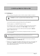
T
o


Attention

:   minimize shock hazard, the instrument chassis and cabinet 

must be connected to an electrical safety ground. This instrument is 
grounded through the ground conductor of the supplied, three-conductor 

AC

 line power cable. The power cable must be plugged into an approved 

three-conductor electrical outlet. 


Attention

 :  When the charger is connected to the appliance, the metallic 

frame is linked to the ground of the electrical installation 

Содержание 902406500

Страница 1: ...RECORDER DAS240 USER S MANUAL Edition April 2017 M240004E...

Страница 2: ...NTY Your instrument is guaranteed for one year for labor and parts against any manufacturing defect and or functioning hazard This guarantee extends from the delivery date and ends 730 calendar days l...

Страница 3: ...any third party without prior authorization by the company voids the guarantee The user shall be responsible for the return of its appliance to our site Hence it shall provide for a conditioning that...

Страница 4: ...months of use and under normal conditions of use We recommend a check after 12 months and max 24 months of use then every 12 months after 24 months For any check of the characteristics the following a...

Страница 5: ...PDATING THE INTERNAL SOFTWARE 3 5 3 4 EXTERNAL POWER 3 5 3 5 BATTERY 3 6 3 6 OFFSET CALIBRATION 3 7 3 7 DEFAULT CALIBRATION 3 7 3 8 DEMO MODE 3 7 4 USE 4 1 DESCRIPTION OF THE UPPER BAND 4 1 4 2 DESCRI...

Страница 6: ...ER 10 5 10 7 CONTROL YOUR DEVICE WITH DASLAB 10 7 11 TECHNICAL SPECIFICATIONS 11 1 GENERAL CHARACTERISTICS 11 1 11 2 TENSION RECORDING 11 1 11 3 RECORD OF THE TEMPERATURE OF THERMOCOUPLE 11 1 11 4 PT1...

Страница 7: ......

Страница 8: ...s live tension Do not alter or defeat the ground connection Without the safety ground connection all accessible conductive parts including control knobs may provide an electric shock Failure to use a...

Страница 9: ...he instrument of the instrument itself Ground accessible parts linked to the ground of the appliance 1 2 1 Conformity and limits of the appliance The DAS240 recorder is in conformity with IEC 61010 1...

Страница 10: ...and the recorder is made easier thanks to an intuitive interface on a wide capacitive and color 10 1 touchscreen The measurement parameters are easy to program The recording is made directly on an int...

Страница 11: ...This period of integration can eliminate noise for high frequency example main noise at 50Hz or engine noise at 1kHz For white noise or noise with lower frequency lower than recording frequency you ca...

Страница 12: ...ng LED 3 ON OFF switch and switching on indicator 4 2 USB connectors for female USB stick 5 RJ45 connector for the Ethernet 10 100 Base interface 6 SUB D 25 pin connector for the 16 logical inputs and...

Страница 13: ...e 2 4 2 2 2 Extension module A module is delivered with the appliance with its 70 cm bounding cable and 20 external terminal blocks Extension cord 70cm 5 08 mm 3 contact step connectors Extension modu...

Страница 14: ...omepage any time in the main menu by pressing the additional option or start screen keys At power up the appliances start with the latest configuration when they were shut down see next paragraph If t...

Страница 15: ...red in each additional extension Assemble the extension modules together Then screw the plates with the adjacent modules Stick the additional adhesive buttress Connect the cable using unlocking levers...

Страница 16: ...utal stop of the power supply the setup will not be saved The appliance setup at next start will be the same as the one of the latest start or of the latest acquisition 3 2 Connection to the measuring...

Страница 17: ...t ref 902406500 50 In this case select the current type among the parameters of the relevant channel Connect the measurement wires to the shunt terminals 3 2 6 Connection of the ground If the source o...

Страница 18: ...on an USB stick Place it on the USB connector on the rear side of the appliance Press the Setup key Then press the Software update key to enter the update Finally to run the update press the Sofware...

Страница 19: ...ry should last 200 charge discharge cycles or 2 years Advice to extend the life of the battery Do not discharge too much Do not store the batteries too long without using them Store the battery at aro...

Страница 20: ...atly 5 minutes Restart the appliance 3 7 Default calibration You can restore the default factory calibration to correct any possible mistake in the calibration coefficients Enter the Electric Calibrat...

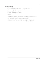
Страница 21: ...dditional Option key Press the Locking the recorder key Confirm The keypad lock will occur 10 seconds after you have pressed the confirmation key All the keys of the appliance will be blocked The Main...

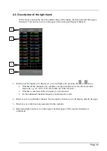
Страница 22: ...use 4 1 Description of the upper band Different areas on the screen 1 Acquisition status in progress stop 2 Battery status if present option 3 Direct access to display 4 Access to the display of the s...

Страница 23: ...ether all the channels of a complete extension module as well as the associated functions e g A1 A20 FA1 FA4 or B1 20 FB1 FA4 etc Whether a customized bloc Custom 1 or Custom 2 Or the additional chann...

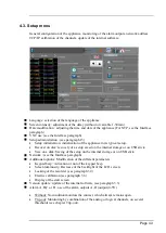
Страница 24: ...recovery of a setup saved on the internal storage or on USB stick Save on a disk Saving of the setup on the internal storage or on USB stick Network see the Interface paragraph Additional options Mod...

Страница 25: ...adjustments of the channels You can change these adjustments directly in this table by pressing the parameter you want to update You can display 10 channels maximum or keys to display other channels...

Страница 26: ...thermocouple o Choice of the thermocouple J K T S B E N C L o Choice of the cold junction compensation o Choice of the unit Celcius Fahrenheit Kelvin Resistance Pt100 Pt1000 o Choice of the number of...

Страница 27: ...igger 1 and 2 the outline of thresholds on the screen is valid in the f t mode a horizontal line allows viewing the threshold Note A warning message displays when the programmed analogic thresholds ar...

Страница 28: ...n acquisition the X and Y channels must be recorded Press the Functions key A summary page of functions assigned to each plug in or key allows to change the view page and to view other functions We ca...

Страница 29: ...ons 4 additional channels K1 to K4 allow to have either the calculation of a frequency or a meter For that In the right band see 4 2 scroll until you reach the K1 to K4 logical functions window Or on...

Страница 30: ...n the left band you must however confirm the logical channels on the channels and function validation screen see 4 8 You access the configuration page of the logical channels After choosing the logica...

Страница 31: ...annel The number of recorded channels gives the minimum sampling period We can also choose the validation of logical channels of functions between channels and of logical channels functions For each p...

Страница 32: ...l page allows to have in real time all channels of the channels groups Plugs in personal group etc The or keys allow to change groups and view other channels For each channel you view The name of the...

Страница 33: ...play on screen Choice of the mode of graphical visualization F t XY Numerical of measurement full screen Full screen to visualize the reticule on full screen f t mode Color to customize the display co...

Страница 34: ...n allows to choose the channels of groups Perso 1 and Perso 2 we choose then 20 channels maximum among all recorded channels The reinitialize channels key cancels the group configuration Freeze the sc...

Страница 35: ...o visualize in real time the values of each channel 1 The or keys allow to choose the group to view 2 By pressing a specific channel o The graph terminals are bound to this channel o In real time acqu...

Страница 36: ...ming the conditions of start and stop of the data acquisition Selection of the actions after data acquisition or plotting and validation of data save in real time See the chapter about data acquisitio...

Страница 37: ...the following window shows up Read file selection of the file to view Write data to file saving the part of the displayed file into another file For big amounts of acquisition data to display recover...

Страница 38: ...The following shows up on the screen current sampling speed status of data acquisition waiting for trigger sampling rate xx 4 15 Screen copy You can create a file copying the content of the LCD screen...

Страница 39: ...changes from negative to positive Level trigger no need to pass the threshold o Example Channel A1 high level threshold 0V triggers only if the signal is positive Alarms only have level triggers Anal...

Страница 40: ...eshold 1 Threshold 2 selection of the threshold to settle each channel is tested with reference with 2 thresholds i e you can program a start condition on the channel A1 and the threshold 1 and a stop...

Страница 41: ...f their respective channels you open the threshold parameter window One of the thresholds or the first achieved condition activates the trigger All thresholds and all conditions must be simultaneously...

Страница 42: ...the trigger condition The 12 logic channels can be used in the trigger word either active at status 0 less than 1 6 volt or active at status 1 more than 4 0 volts or non used X AND OR the logic funct...

Страница 43: ...ulations Then press the Mathematical calculations key Selection of the number of calculations Channel selection of the channel where the calculation is made Function selection of the calculation funct...

Страница 44: ...type of calculation the value of calculation You can place this window anywhere on the screen click slide Under Direct display calculations are made in real time and the display is updated every 300m...

Страница 45: ...elow the median High The most frequent value above the median Amplitude High Low On positive oscillation 100 Amplitude High Max On negative oscillation 100 Amplitude Min Low Frequency Period 1 Average...

Страница 46: ...Width of negative impulsion Measurement of the time of 1st negative pulse It is measured at 50 of amplitude Positive cyclic ratio period duration pulse positive Negative cyclic ratio period duration...

Страница 47: ...data acquisition Manual by pressing a key Trigger on a channel or a combination of analogic or logic channels see 5 Waiting after a delay or at a specified date and hour Automatic immediate automatic...

Страница 48: ...f the trigger is in automatic mode the data acquisition starts On the upper left of the screen appear the name of the file the current sampling speed the data acquisition state waiting for trigger The...

Страница 49: ...rt of the data or change of page Keys of the Display menu Total the complete memory is displayed and update during the acquisition Partial only a part of the memory is displayed the screen is frozen o...

Страница 50: ...al cursors Channel value cursors horizontal cursors 7 Zoom between cursors makes it possible to zoom between the positioned cursors Zoom and Zoom make it possible to zoom or unzoom onto a part of the...

Страница 51: ...alues X 2 Display of the cursors 3 Selection of the channel where to apply the cursor 4 Zoom between cursors 5 Manual change of the caliber position of the channel 6 Return to the initial calibers pos...

Страница 52: ...disk or an USB stick if it was connected at the start of the appliance 2 Copy of a file to USB copy the selected file or folder to an USB peripheral 3 Type the name of a new file 4 Create folder crea...

Страница 53: ...e internal flash disk or an USB stick 8 2 1 Save Setup files Press Save to disk You can type the name of the file with the alphanumerical keyboard displayed on screen Advice Do not save files to the r...

Страница 54: ...place and name of the file to load and display on screen then press Load configuration make it possible to load the configuration of the appliance when the file was created The pending configuration o...

Страница 55: ...Logic channel 5 23 Logic channel 6 10 Logic channel 7 22 Logic channel 8 9 Logic channel 9 21 Logic channel 10 8 Logic channel 11 20 Logic channel 12 7 Logic channel 13 19 Logic channel 14 6 Logic cha...

Страница 56: ...splayed at the top or the bottom of the screen according to the selected position They are numbered from the right to the left Each channel is plotted between two dotted lines that show their limits T...

Страница 57: ...the charge and 15V is the charger is connected The ground of this power supply is the mechanical ground Thus you can use this output to provide power to a sensor or an electronic circuit in order to m...

Страница 58: ...according to the signal tension 0 to 250V connection 0 250V logic channel red black by insulated pin plug between red and black terminals max usable tension 250V continuous or alternating typical trip...

Страница 59: ...10ms Typical delay for a falling signal 50ms Use Link the box to the input output connector of the appliance with the 25 pin connector provided as an option Connect the logic channels to record with r...

Страница 60: ...cal channel 1 8 Blue L9 L16 8 Logical channel 9 16 Yellow AL1 AL4 4 See below DAS240 Mark K1 L13 Logical function K1 K2 L14 Logical function K2 K3 L15 Logical function K3 K4 L16 Logical function K4 DA...

Страница 61: ...ocol to dialog with the PC Thus you can give it an IP address with a subnet mask Ask your network administrator an IP address and a corresponding mask then when you have Setup the recorder with the SE...

Страница 62: ...graphs to the recorder 10 2 WIFI interface Use only the USB stick provided by SEFRAM Turn the appliance on with the USB stick on a relevant port In the Setup menu press the Network key Once the Wi Fi...

Страница 63: ...ou recorded your data acquisitions you can rename them move them copy them or erase them Transfer your files to your computer to use them with the provided SeframViewer software or FLEXPRO You cannot...

Страница 64: ...to the applications you need Just open the VNC viewer file where you recorded it On the VNC Server line you must type the IP address of your recorder and the password the default password is sefram th...

Страница 65: ...rotocol Launch the SeframViewer software or double click on a file Open a data acquisition file suffix rec You can select the channels to display the display mode f t or xy the self calibration of the...

Страница 66: ...m Files x86 SeframViewer seframviewer exe myfile rec x will create a xls file C Program Files x86 SeframViewer seframviewer exe myfile rec t will create a txt file Excel export will directly launch Ex...

Страница 67: ...les using network via Ethernet or WiFi DASLaB is available on the sefram website http www sefram com en products recorders dataloggers DAS240 multi channel handheld recorder html According to your nee...

Страница 68: ...n current through external shunt Thermocouple J K T S B N E C L Pt100 Pt1000 Resistance 11 2 Tension recording max caliber 200 V 100 V to 100 V min caliber 1 mV 0 5 mV to 0 5 mV accuracy 0 1 of full s...

Страница 69: ...1 of the measurement value 11 5 Resistance Probe Record 2 input ranges 1k Current generator 1mA Accuracy 1 10k Current generator 100 A Accuracy 10 11 6 Sampling Polling system one sample per valid ch...

Страница 70: ...10Hz to 10kHz o Accuracy 0 1 PWM o Frequency 100Hz to 2kHz o Accuracy 0 1 11 7 2 Logic channels Number of channels 12 Input impedance 4 7k max sampling frequency 1 kHz 1ms max possible tension 24V cat...

Страница 71: ...ion see 11 6 11 10 Communication interface 11 10 1 Ethernet Speed 10 100 base T Connector RJ45 DHCP possible FTP server VNC server NTP client Remote control Protocol TCP IP Connection port 23 11 10 2...

Страница 72: ...m Height 175mm Weight 1 5kg 2kg with battery 20 channel module Depth 196mm Width 67mm Height 23mm Weight 0 2kg 11 12 Security insulation class installation category Security class handy appliance for...

Страница 73: ...or connector 214299014 Extension box with accessory set 902401000 11 13 2 Accessories and options Transportation briefcase 902408000 Internal battery 902405000 Shunt 50 0 01 0 5W 902406500 Box for log...

Страница 74: ...easurement range between 50 and 50 C with a J thermocouple Max absolute value T 50 C Add 40 C T 40 90 C Corresponding U tension according to the tables ThJ U 4 726 mV Programmed caliber 10 mV measurem...

Страница 75: ...perature but this variation is generally of the second order for the accuracy calculation Tension of thermocouple mV Slope of the thermocouples V Example At 100 C the slope of thermocouple J is 55 V A...

Страница 76: ...with compensation of cold welding Pt Pl Ps Pm Pl 0 25 C linearization accuracy Ps 0 5 C compensation of cold welding Used caliber 10mV see previous example Accuracy for tension measurement 0 1 10mV 1...

Страница 77: ...absolute value ex 5 V for the first calibers The variations of the measured value with the variations of one of the influential variables in the nominal range of use do not exceed C for the position...

Страница 78: ......
Отзывы: