background image

Lesson 2: Pressing Button to Light Up LED

The first thing we need to know is that the input of the button is a digital signal, and there are only
two states, 0 or 1, so we can control the output based on those two states.

Practice: Use button to turn ON and OFF the LED module

Components Involved

1. Seeeduino Lotus
2. Grove LED
3. Grove Button
4. Grove Cables(If broken out)

Hardware connection

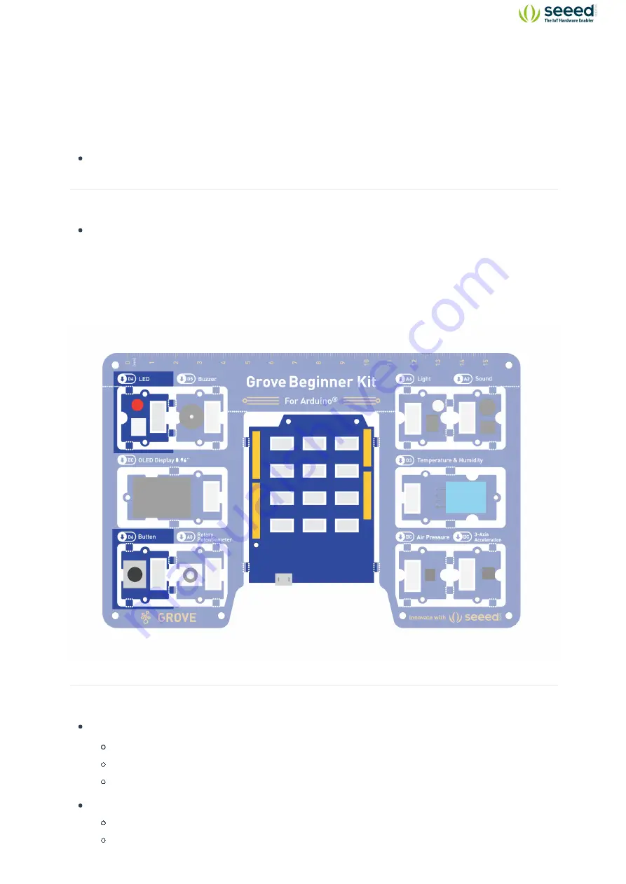
Module connection:
Default connection by PCB stamp hole.
The Seeeduino is then connected to the computer via a USB cable.

Hardware analysis:

Input: Button
Control: Seeeduino

15

Grove Beginner Kit For Arduino

®

Содержание Grove Beginner Kit

Страница 1: ...Grove Beginner Kit For Arduino User Manual ...

Страница 2: ...mple LED module 2 Grove Buzzer Piezo Buzzer 3 Grove OLED Display 0 96 128 64 dot resolution High brightness self emission and high contrast ratio Big screen on a compact design Low power consumption 4 Grove Button Push button for human input interfaces 5 Grove Rotary Potentiometer Rotary knob for human input interfaces 6 Grove Light Detects surrounding light intensity 7 Grove Sound Detects surroun...

Страница 3: ...esson 3 Controlling the Speed of the Blink 24 Lesson 4 Making the Buzzer go BEEP 28 Lesson 5 Making an Light Induct LED 35 Lesson 6 Sound Sensitive LED Light 41 Lesson 7 Displaying Data on OLED 47 Lesson 8 Detecting Temperature Humidity 51 Lesson 9 Measuring Air Pressure 55 Lesson 10 Sensing Movement 60 Project 1 Music Dynamic Rhythm Lamp 64 Project 2 Sound Light Induction Lamp 69 Resources 70 Mor...

Страница 4: ...ound Analog A2 Temperature Humidity Sensor Digital D3 Air Pressure Sensor I2C I2C 0x77 default 0x76 optional 3 Axis Accelerator I2C I2C 0x63 default Breakout Instruction Attention Please be careful not to cut your hands when using a knife If you prefer to use the modules in elsewhere then you can simply follow the procedures to break the modules out Step 1 Use a knife or a sharp object to cut at t...

Страница 5: ...nsors x1 3 Axis Accelerometers x1 Air Pressure x1 Light Sensor x1 Sound Sensor x1 Input Modules Rotary Potentiometer x1 Button x1 Output Modules LED x1 Buzzer x1 Display Module OLED Display x1 Grove Cables x6 Micro USB Cable x1 4 Grove Beginner Kit For Arduino ...

Страница 6: ...Demo The Grove Beginner Kit has a plug and plays unboxing demo where you first plug in the power to the board you get the chance to experience all the sensors in one go Use the button and rotary potentiometer to experience each sensor demo Scroll Rotating Rotary Potentiometer Select Short Press Button Exit Current Demo Long Press Button Buzzer and LED module are used for key prompt 5 Grove Beginner...

Страница 7: ...back of the development board Download the CP2102 USB Driver Note Download according to your OS After the driver installation is completed connect Arduino to the USB port of PC with a USB cable For Windows users You can see it in My Computer Properties Hardware Device Management A COM will appear For Mac OS users You can navigate to on the top left corner and choose About this Mac System Report US...

Страница 8: ...e correct Development Board Model Select Arduino Genuino Uno as Board 3 Click Tools Port to select the correct Port the Serial Port showed in Device Manager in the previous step In this case COM6 is selected For Mac OS users it should be dev cu SLAB_USBtoUART 7 Grove Beginner Kit For Arduino ...

Страница 9: ... there are two buttons Verify and Upload First press the Verify button to compile After the compilation is successful press the upload button 6 Navigate to Tools Serial Monitor or click the Serial Monitor in the upper right corner Magnifier Symbol you can see the program running results Note If you installed the portable Arduino IDE from our USB Drive you can find all the module demos in the Files S...

Страница 10: ...re wired on a single circuit board so no cables and soldering are needed However if you break out the modules and want to connect them with Grove cables please kindly check the Breakout Guide 9 Grove Beginner Kit For Arduino ...

Страница 11: ... unit the LED module is the output unit and the output signal is a digital signal Background Information What is Digital Signal Digital signal Digital signal refers to the value of the amplitude is discrete the amplitude is limited to a finite number of values In our controller the digital signal has two states LOW 0V for 0 HIGH 5V for 1 So sending a HIGH signal to LED can light it up Components In...

Страница 12: ...E Copy the following code click Verify to check for syntax errors Verify that there are no errors and you can upload the code LED Blink The LED will turn on for one second and then turn off for one second int ledPin 4 void setup pinMode ledPin OUTPUT void loop digitalWrite ledPin HIGH delay 1000 digitalWrite ledPin LOW delay 1000 11 Grove Beginner Kit For Arduino ...

Страница 13: ...ly control the Arduino board int ledPin 4 Description Converts a value to the int data type Syntax int x or int x C style type conversion Parameters x a value Allowed data types any type Assigned an int type 4 to variable named ledPin pinMode ledPin OUTPUT Description Configures the specified pin to behave either as an input or an output See the Digital Pins page for details on the functionality of ...

Страница 14: ...al Pins tutorial for more information If you do not set the pinMode to OUTPUT and connect an LED to a pin when calling digitalWrite HIGH the LED may appear dim Without explicitly setting pinMode digitalWrite will have enabled the internal pull up resistor which acts as a large current limiting resistor Syntax digitalWrite pin value Parameters pin the Arduino pin number value HIGH or LOW When we se...

Страница 15: ...ay the program by 1000ms 1s Demo Effect and Serial Print Result The LED module will be 1 second on and 1 second off Breakout Guide If modules are broken out from the board Use a Grove cable to connect the Grove LED to Seeeduino Lotus s digital interface D4 14 Grove Beginner Kit For Arduino ...

Страница 16: ...sed on those two states Practice Use button to turn ON and OFF the LED module Components Involved 1 Seeeduino Lotus 2 Grove LED 3 Grove Button 4 Grove Cables If broken out Hardware connection Module connection Default connection by PCB stamp hole The Seeeduino is then connected to the computer via a USB cable Hardware analysis Input Button Control Seeeduino 15 Grove Beginner Kit For Arduino ...

Страница 17: ...the number of the pushbutton pin const int ledPin 4 the number of the LED pin variables will change int buttonState 0 variable for reading the pushbutton statu s void setup initialize the LED pin as an output pinMode ledPin OUTPUT initialize the pushbutton pin as an input pinMode buttonPin INPUT void loop read the state of the pushbutton value buttonState digitalRead buttonPin check if the pushbut...

Страница 18: ...Code Analysis pinMode ledPin OUTPUT Define LED as the output unit pinMode buttonPin INPUT Define button as the input unit 17 Grove Beginner Kit For Arduino ...

Страница 19: ...rouped An else clause if at all exists will be executed if the condition in the if statement results in false The else can proceed another if test so that multiple mutually exclusive tests can be run at the same time Each test will proceed to the next one until a true test is encountered When a true test is found its associated block of code is run and the program then skips to the line following ...

Страница 20: ...te the statement in curly braces after the else If the state of the button is high the LED pin outputs a high level and turn the LED on else turn LED off Demo Effect and Serial Print Result Pressing the button will turn the LED module on Breakout Guide Use a Grove cable to connect the Grove LED to Seeeduino Lotus s digital interface D4 Connect the Grove Button to digital interface D6 19 Grove Beginn...

Страница 21: ...l Analog signals Signals vary continuously in time and value and the amplitude frequency or phase of the signal changes continuously at any time such as the current broadcast sound signal or image signal etc The analog signal has sine wave and triangle wave and so on The analog pins of your microcontroller can have between 0V and 5V is mapped to a range between 0 and 1023 where 1023 is mapped as 5...

Страница 22: ...nnected to the computer via a USB cable Hardware analysis Input Rotary Potentiometer Control Seeeduino Lotus Output LED module The input is an analog signal so it is connected to the analog signal interface the LED module is connected to the digital signal interface 21 Grove Beginner Kit For Arduino ...

Страница 23: ...LED int rotaryValue 0 variable to store the value coming from the rota ry void setup declare the ledPin as an OUTPUT pinMode ledPin OUTPUT void loop read the value from the sensor rotaryValue analogRead rotaryPin turn the ledPin on digitalWrite ledPin HIGH stop the program for sensorValue milliseconds delay rotaryValue turn the ledPin off digitalWrite ledPin LOW stop the program for for sensorValu...

Страница 24: ...Although it is limited to the resolution of the analog to digital converter 0 1023 for 10 bits or 0 4095 for 12 bits Data type int This function is used to read the value of Analog pins the rotary sensor position the range of values is 0 1023 delay rotaryValue Delay function The millisecond duration of the delay is the value in parentheses Because the value is the value of the analog signal of the...

Страница 25: ...an simulate voltages in between full on 5 Volts and off 0 Volts by changing the portion of the time the signal spends on versus the time that the signal spends off The duration of on time is called the pulse width To get varying analog values you change or modulate that pulse width If you repeat this on off pattern fast enough with an LED for example the result is as if the signal is a steady voltage...

Страница 26: ...eeduino Lotus 2 Grove Buzzer 3 Grove Cable If Broken out Hardware connection Module connection Default connection by PCB stamp hole Connect the Seeeduino to the computer through the USB cable 25 Grove Beginner Kit For Arduino ...

Страница 27: ...ors and you can upload the code int BuzzerPin 5 int Potentiometer A0 void setup pinMode BuzzerPin OUTPUT void loop int potentioValue Value potentioValue analogRead Potentiometer Value map potentioValue 0 1023 0 255 Mapping potentiometer va lue to PWM signal value analogWrite BuzzerPin Value 26 Grove Beginner Kit For Arduino ...

Страница 28: ...igitalRead or digitalWrite on the same pin Syntax analogWrite pin value Parameters pin the Arduino pin to write to Allowed data types int value the duty cycle between 0 always off and 255 always on Allowed data types int Writes an analog value PWM wave to the Buzzer Demo Effect and Serial Print Result The buzzer beeps 3 times fast at startup waits a second then beeps continuously at a slower pace Br...

Страница 29: ...In the following sections we will use Serial Monitor to observe results from our sensors so here comes the brief introduction Background Information What is Serial Monitor Serial Monitor is a useful tool to observe results on Arduino it can be very useful in terms of printing results from the sensors or debugging in general You can also send data back to the controller via the serial monitor to do...

Страница 30: ... light slowly dimmed the LED dimmed The LED will go from dark to light or from light to dark To achieve this we will use pulse width modulation PWM Components Involved 1 Seeeduino Lotus 2 Grove LED 3 Grove Light Sensor 4 Grove Cable If broken out 29 Grove Beginner Kit For Arduino ...

Страница 31: ...e connection Default connection by PCB stamp hole The Seeeduino is then connected to the computer via a USB cable Hardware analysis Input Light Sensor Control Seeeduino Lotus Output LED module 30 Grove Beginner Kit For Arduino ...

Страница 32: ...the port int outputValue 0 value output to the PWM analog out void setup pinMode ledPin OUTPUT Serial begin 9600 void loop read the analog in value sensorValue analogRead sensorpin map it to the range of the analog out outputValue map sensorValue 0 1023 0 255 Serial println sensorValue change the analog out value analogWrite ledPin outputValue delay 30 You can also see the light intensity readings...

Страница 33: ...aud rate is 9600 Syntax Serial begin speed Parameters speed Speed of Serial communication i e 9600 115200 and etc Set the Serial baud rate to 9600 Serial println sensorValue Description Prints data to the serial port as human readable ASCII text followed by a carriage return character ASCII 13 or r and a newline character ASCII 10 or n This command takes the same forms as Serial print Syntax Seria...

Страница 34: ...es integer math so will not generate fractions when the math might indicate that it should do so Fractional remainders are truncated and are not rounded or averaged Syntax map value fromLow fromHigh toLow toHigh Parameters value the number to map fromLow the lower bound of the value s current range fromHigh the upper bound of the value s current range toLow the lower bound of the value s target ra...

Страница 35: ...the LED Demo Effect and Serial Print Result The LED module will change its intensity according to the light intensity of the surrounding The darker the surrounding the lighter it gets Breakout Guide Use Grove Cable to connect the Grove LED to Seeeduino Lotus s digital signal interface D4 connect the Grove Light Sensor to Seeeduino Lotus s analog signal interface A1 34 Grove Beginner Kit For Arduino...

Страница 36: ... with the basics this experiment will be easy for you Here used Serial Plotter to visualize results Background Information What is Serial Plotter Serial Plotter is similar to Serial Monitor allowing you to natively graph serial data from your Arduino to your computer in real time This is very useful when data needs to be visualized You can open the Serial Plotter by clicking Tools Serial Plotter 3...

Страница 37: ...ght up when the sound is made When there is no sound and it is very quiet the LED lights go off Components Involved 1 Seeeduino Lotus 2 Grove LED 3 Grove Sound Sensor 4 Grove cable If broken out 36 Grove Beginner Kit For Arduino ...

Страница 38: ...Hardware connection Module connection Default connection by PCB stamp hole The Seeeduino is then connected to the computer via a USB cable 37 Grove Beginner Kit For Arduino ...

Страница 39: ...al void setup pinMode ledPin OUTPUT Serial begin 9600 void loop int soundState analogRead soundPin Read sound sensor s value Serial println soundState if the sound sensor s value is greater than 200 the light will be o n for 5 seconds Otherwise the light will be turned off if soundState 200 digitalWrite ledPin HIGH delay 100 else digitalWrite ledPin LOW You can also see the light intensity reading...

Страница 40: ...board and the baud rate is 9600 Serial print This function is used to output data from the serial port the output is what is contained in the double quotation marks Serial println This statement is similar to the one above except that serial println has a newline return 39 Grove Beginner Kit For Arduino ...

Страница 41: ...lue of the output sensor Demo Effect and Serial Print Result The LED module will light up if the surrounding is loud enough Breakout Guide Use Grove cables to connect the Grove LED to Seeeduino Lotus s digital signal interface D4 Connect the Grove Sound Sensor to Seeeduino Lotus s analog signal interface A2 40 Grove Beginner Kit For Arduino ...

Страница 42: ...he use of libraries just like most other programming platforms Libraries provide extra functionalities for use in sketches i e working with specific hardware or manipulating data To use a library in a sketch select it from Sketch Include Library For more information please also visit How to install Arduino Libraries Components Involved 1 Seeeduino Lotus 2 Grove OLED 3 Grove cable If broken out 41 G...

Страница 43: ...Hardware connection Module connection Default connection by PCB stamp hole The Seeeduino is then connected to the computer via a USB cable 42 Grove Beginner Kit For Arduino ...

Страница 44: ... following code click Verify to check for syntax errors Verify that there are no errors and you can upload the code include Arduino h include U8x8lib h U8X8_SSD1306_128X64_ALT0_HW_I2C u8x8 reset U8X8_PIN_NONE void setup void u8x8 begin u8x8 setFlipMode 1 void loop void u8x8 setFont u8x8_font_chroma48medium8_r u8x8 setCursor 0 0 u8x8 print Hello World 43 Grove Beginner Kit For Arduino ...

Страница 45: ...efine Description define is a useful C component that allows the programmer to give a name to a constant value before the program is compiled Defined constants in Arduino don t take up any program memory space on the chip The compiler will replace references to these constants with the defined value at compile time Force a variable to be the value you want U8X8_SSD1306_128X64_ALT0_HW_I2C u8x8 reset ...

Страница 46: ... setFlipMode mode Parameters mode 0 or 1 Flips the display 180 degrees u8x8 setCursor Description Define the cursor for the print function Any output of the print function will start at this position Syntax u8x8 setCursor x y Parameters x y Column row position for the cursor of the print function Sets the draw cursor position u8x8 setFont Description Define a u8x8 font for the glyph and string drawi...

Страница 47: ...Prints Hello World onto the OLED Display Breakout Guide Use Grove cable to connect the OLED to Seeeduino Lotus s I2C interface Note I2C s default address is 0x78 46 Grove Beginner Kit For Arduino ...

Страница 48: ...addressing at this time is considered from the device The relationship between master and slave sender and receiver on the bus is not constant but depends on the direction of data transmission If the host wants to send data to the slave device the host first addresses the slave device then actively sends data to the slave device and finally terminates the data transmission by the host If the host is...

Страница 49: ...Hardware connection Module connection Default connection by PCB stamp hole The Seeeduino is then connected to the computer via a USB cable 48 Grove Beginner Kit For Arduino ...

Страница 50: ...sor include DHT h include Arduino h include U8x8lib h define DHTPIN 3 what pin we re connected to define DHTTYPE DHT11 DHT 11 DHT dht DHTPIN DHTTYPE U8X8_SSD1306_128X64_ALT0_HW_I2C u8x8 reset U8X8_PIN_NONE void setup void Serial begin 9600 Serial println DHTxx test dht begin u8x8 begin u8x8 setPowerSave 0 u8x8 setFlipMode 1 void loop void float temp humi temp dht readTemperature humi dht readHumid...

Страница 51: ...type float Call these functions to read the temperature and humidity and store them in defined variables Demo Effect and Serial Print Result The surrounding temperature and humidity appear on the OLED screen Breakout Guide Use Grove cable to connect the OLED to Seeeduino Lotus s I2C interface Note I2C s default address is 0x78 Connect the Grove Temperature and Humidity Sensor to Seeeduino Lotus s dig...

Страница 52: ... and atmospheric pressure accurately As the atmospheric pressure changes with altitude it can also measure the approximate altitude of a place Components Involved 1 Seeeduino Lotus 2 Grove Air Pressure Sensor 3 Grove cable if broken out Hardware connection Module connection Default connection by PCB stamp hole The Seeeduino is then connected to the computer via a USB cable 51 Grove Beginner Kit Fo...

Страница 53: ...e result Air pressure detection include Seeed_BMP280 h include Wire h BMP280 bmp280 void setup Serial begin 9600 if bmp280 init Serial println Device not connected or broken void loop float pressure get and print temperatures Serial print Temp Serial print bmp280 getTemperature Serial println C The unit for Celsius because original arduin o don t support speical symbols get and print atmospheric p...

Страница 54: ...he air pressure sensor Syntax bmp280 init if the Air pressure sensor did not start properly then prints out an error to the serial monitor Serial print bmp280 getTemperature Description Functions to be used to read temperature value from the sensor Syntax bmp280 getTemperature Return type float Prints the temperature data to the serial monitor Serial print pressure bmp280 getPressure Description Fu...

Страница 55: ...oat Return type float Parameter float Pressure value Prints the amplitude Demo Effect and Serial Print Result The Air pressure readings are display on the Serial Monitor Breakout Guide Use Grove cable to connect Grove 3 axis Accelerometer to Seeeduino Lotus s I2C interface using a Grove cable note I2C default address is 0x77 or 0x76 54 Grove Beginner Kit For Arduino ...

Страница 56: ...ments on the basis of the motion Practice when motion is detected the buzzer gives an alarm indicating that the object is in motion Components Involved 1 Seeeduino Lotus 2 Grove 3 axis Accelerometer 3 Grove cable if broken out Hardware connection Module connection Default connection by PCB stamp hole The Seeeduino is then connected to the computer via a USB cable 55 Grove Beginner Kit For Arduino ...

Страница 57: ...eck the result Gravity Acceleration include LIS3DHTR h ifdef SOFTWAREWIRE include SoftwareWire h SoftwareWire myWire 3 2 LIS3DHTR SoftwareWire LIS I2C_MODE IIC define WIRE myWire else include Wire h LIS3DHTR TwoWire LIS I2C_MODE IIC define WIRE Wire endif void setup Serial begin 9600 while Serial LIS begin WIRE IIC init delay 100 LIS setOutputDataRate LIS3DHTR_DATARATE_50HZ void loop if LIS Serial...

Страница 58: ...RE LIS setOutputDataRate LIS3DHTR_DATARATE_50HZ Description Initialize the accelerator Syntax LIS begin Wire Description Sets the output data rate of the accelerator Syntax LIS setOutputDataRate odr_type_t odr Initialize the accelerator and set the output rate to 50Hz Serial print x Serial print LIS getAccelerationX Serial print Serial print y Serial print LIS getAccelerationY Serial print Serial ...

Страница 59: ...r Syntax LIS getAccelerationZ Return type float Prints the 3 axis data to the serial monitor Demo Effect and Serial Print Result The 3 axis accelerator readings are displayed on the Serial Monitor Breakout Guide Use Grove cable to connect Grove 3 axis Accelerometer to Seeeduino Lotus s I2C interface using a Grove cable note I2C default address is 0x4c 58 Grove Beginner Kit For Arduino ...

Страница 60: ...usic and the led lights flash according to the music frequency and beat Components Involved 1 Seeeduino Lotus 2 Grove LED 3 Buzzer 4 Grove Cables if broken out Hardware connection Module connection Default connection by PCB stamp hole The Seeeduino is then connected to the computer via a USB cable 59 Grove Beginner Kit For Arduino ...

Страница 61: ...TDL3 175 define NTDL4 196 define NTDL5 221 define NTDL6 248 define NTDL7 278 define NTDH1 589 define NTDH2 661 define NTDH3 700 define NTDH4 786 define NTDH5 882 define NTDH6 990 define NTDH7 112 define WHOLE 1 define HALF 0 5 define QUARTER 0 25 define EIGHTH 0 25 define SIXTEENTH 0 625 int tune NTD3 NTD3 NTD4 NTD5 NTD5 NTD4 NTD3 NTD2 NTD1 NTD1 NTD2 NTD3 NTD3 NTD2 NTD2 NTD3 NTD3 NTD4 NTD5 NTD5 NT...

Страница 62: ...1 1 0 5 0 5 1 1 1 0 5 0 5 1 1 1 1 1 1 1 1 1 1 1 1 1 0 5 0 5 1 1 1 1 1 0 5 0 5 1 1 int length int tonepin 5 int ledp 4 void setup pinMode tonepin OUTPUT pinMode ledp OUTPUT length sizeof tune sizeof tune 0 void loop for int x 0 x length x tone tonepin tune x digitalWrite ledp HIGH delay 400 durt x digitalWrite ledp LOW delay 100 durt x noTone tonepin delay 4000 61 Grove Beginner Kit For Arduino ...

Страница 63: ...62 Grove Beginner Kit For Arduino ...

Страница 64: ...1 Half beat is 0 5 1 4 beat is 0 25 1 8 of 0 125 int tune List the frequencies according to the spectrum float durt List the beats according to the spectrum delay 100 durt x Control LED lights on and off respectively Demo Effect and Serial Print Result The buzzer will beep a tune while the LED module will flicker with same frequency Breakout Guide Connect Grove LED to Seeeduino Lotus s digital signal...

Страница 65: ...able In this way you can achieve the function of the smart desk lamp when the sound the lamp will light up If the environment turns dark the lamp will automatically turn brighter Components Involved 1 Seeeduino Lotus 2 Grove LED 3 Light Sensor 4 Sound Sensor 5 Grove cable If broken out Hardware connection Module connection Default connection by PCB stamp hole The Seeeduino is then connected to the...

Страница 66: ... 10 the light will be on Otherwise the light will be turned off if soundState 50 lightState 10 digitalWrite ledPin HIGH delay 5000 You can delete the to make the LED on for five se conds else digitalWrite ledPin LOW Code Analysis if soundState 50 lightState 10 In parentheses is a logical expression Both and are commonly used in logical expressions The common usage is if expression 1 expression 2 a...

Страница 67: ...eeduino Lotus s digital signal interface D4 Connect the Light Sensor to Seeeduino Lotus s analog signal interface A1 Connect the Sound Sensor to Seeeduino Lotus s analog signal interface A2 using a Grove cable 66 Grove Beginner Kit For Arduino ...

Страница 68: ... Gerber output The suite runs on Windows Linux and macOS and is licensed under GNU GPL v3 Geppetto If you don t want to work on schematic or layout yourself but you want to convert your prototype based on Seeed s modules into an integrated product we highly recommend you to try Geppetto Geppetto is by far the easiest and least expensive way to produce production quality electronics You don t need ...

Страница 69: ... Fusion PCBA Service To speed up the process of PCB design Seeed is building the component libraries for KiCad and Eagle When all components are sourced from Seeed s PCBA OPL and used with the Seeed Fusion PCB Assembly PCBA service the entire PCBA production time can be reduced from 20 working days to a mere 7 days 68 Grove Beginner Kit For Arduino ...

Страница 70: ...F 2 Grove Beginner Kit for Arduino Schematic Design Files 3 Modules Libraries on Github OLED Display Temperature Humidity Sensor Air Pressure Sensor 3 Axis Accelerator 4 Sensor Datasheet 5 Initial Arduino Firmware Demo 69 Grove Beginner Kit For Arduino ...

Страница 71: ...More Learning LSTM for live IoT data prediction Tech Support Please submit any technical issue into our forum 70 Grove Beginner Kit For Arduino ...

Отзывы: