G Sub 1001 dp+
4 Connectors/Indicators
7
4.2
Connectors
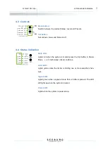
XLR connectors (1)
The G Sub 1001 dp+ should be connected with a standard symmetrically wired XLR cable. To
connect the input signal to further devices, use the male XLR Loop thru connector. To obtain full
power performance from the system, the signal source should be able to provide a minimum of 6
dBu distortion free output voltage.
PowerCon blue (2)
Power supply input voltage 110-230 VAC. This connector provides the function of an on-off switch.
After powering on (turn the connector to the right until it locks), the systems starts up and is ready
for use after approximately 3 seconds. Avoid repeatedly switching the system on and off, particu-
larly when it is operating.
PowerCon grey (3)
110-230 VAC loop-through connector. This connector is to be used when multiple active loud-
speakers are to be provided with power from one source. Please observe carefully the maximum
power capacity of the power source.
The nominal power consumption of the G Sub 1001 dp+ under full
power is 0.75 A (measured with pink noise, Crest Factor 8). Transient
peaks can, however, cause much higher momentary power drain.
Observe carefully the nominal power consumption when connecting
the loudspeaker(s) to the power source, and observe carefully the
cut-off current of the safety circuit breakers. We recommend using the
loudspeaker on power circuits with circuit breakers with C characteris-
tic.
SpeakON black (4) – Parallel LS output
This connector is used to connect and power a further external G Sub 1001 from the first amplifier
channel parallel to the built in loudspeaker (pin assignment 2+/-). The output signal from the se-
cond amplifier channel is present here on pins 1+/- to enable the implementation of system cabling.
ATTENTION
!
The total impedance of the connected passive systems must be 8 Ohm or more! It
is highly recommended to not connect more than one passive G Sub 1001 to this output.


