


9
2 Installation
2.1 Device Installation
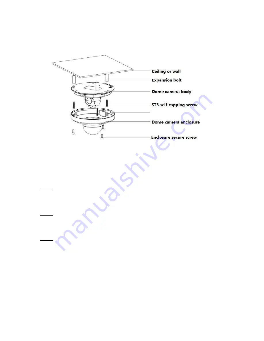
Figure 2-1 Device installation illustration 1
Important
Please make sure the installation surface can support at least 3 times the weight of the
camera and the bracket.
Please refer to the steps listed below.
Step1
Use the inner hexagonal wrench (provided) to loosen the three inner hexagon screws in the
outer dome cover and then remove the cover.
Step 2
Locate the installation template in the accessories bag, and affix it to the ceiling or wall
according to your monitor area requirements.
Step 3
Drill 3 holes, 3/16” diameter as indicated at the marks on the template. Remove the template
and insert the 3 included plastic expansion anchors in the holes.
Note:
If the cable must exit behind the installation surface (behind a wall or inside the ceiling),
Drill a ¾” cable exit hole in the mounting surface according to the installation template.
If the cable must exit the camera on the surface of the wall or ceiling, use a strong needle-
nose plier or similar tool to pry out and remove the thin metal of the camera
’
s outer shell, as
shown in Figure 2-1 above;
“
Remove this for surface-cable use
”
.
Remove this for surface-cable use


