

Step 2
Turn counter clockwise to remove the decoration ring.
Please drill a “cable exit hole” in the surface according
to the installation position map if you want to draw
out the cable from the top of the installation surface.
You need to draw out the cable from the cable channel
side port of the pedestal if you want to draw out the
cable from the side port of the cable channel. Adjust
the device installation pedestal to the proper position
and then draw the cable through the cable exit. Line up
the three screw holes in the installation position. Put
the three self-tapping screws in the three plastic
expansion bolts firmly. Now the dome camera is secure
in the installation surface.
Step 3
Adjust the lens to get a clear view of the area you want
to monitor.
Cross-head Screwdriver
Adjustment Screw
Step 4
Line up the decoration ring to the neck of the camera
body and tighten in place. Push and then turn
decoration ring clockwise. The installation is completed
after you secure the decoration ring. You need to use the
proper tool to open up the side port of the U-cable
channel of the decoration ring if you want to draw out
the cable from the side port of the cable channel when
you are installing the device cable. Then you can draw
out the cable from the cable channel of the pedestal.
Finally you can install the decoration ring to complete
the installation.
The dome camera is usually installed on a ceiling.
Although, It could also be installed on a wall. you
secure the screws on the pedestal, please pull the cable
through the cable exit of the pedestal.
Do not remove the electrostatic film until the
installation is completed. After you remove the film, do
not touch the enclosure in case there is any scratch.
Ceiling or Wall
Installation Position Map
Expansion Bolts
Self-Tapping Screw
Enclosure fastening screw
Inner Hex Wrench
HD-CVI Glass Housing
Step 1
Take the installation position map from the accessories
bag and put it on the surface of the ceiling or the wall
according to the cable exit position. Drill three holes
according to the installation position map and then take
three expansion bolts from the accessories bag and put
them into the holes you just drilled.
Fastening Screw
Step 2
Use the inner hex wrench to remove the three enclosure
fastening screws and then remove the dome enclosure.
Step 3
Adjust the pedestal position according to the cable exit
move(ceiling/side). Pull the cable through the cable
side exit at the installation surface and the pedestal.
(Please skip this step if you are mounting on a ceiling).
Line up the screw holes at the bottom of the pedestal to
the expansion bolts in the installation surface. Put three
self-tapping screws to expansion bolts and then secure
firmly. Now the pedestal is on installation surface.
Step 4
Adjust the camera module angle to a proper position
and then fix the screws to fasten.
Step 5
Use three enclosure fastening screws to secure the dome
housing on the pedestal.
4
Bullet Framework
Important
Dimensions of Cameras may vary depending on your
model. If you are having trouble finding the dimensions
you can find the measurements by using a caliper or try
your best using a ruler. To find the circumference of the
bottom of the camera use the following formula:
Diameter of circle x 3.14(pi)
Sun Shield Cover
Lens
Bracket
5
Bullet Installation
2 Megapixel Camera
Step 1
Before you install the bracket, please pull the cable
through the cable exit of the bracket chassis. install the
expansion bolt if you want to install in cement wall
and then you can install the bracket. If you want to
install in a wood surface, please skip the first step and
then use the self-tapping screws to install the bracket
directly
Important
Before the installation, please make sure the installation surface
can sustain at least 3X weight of the bracket and the camera.
Step 2
Unscrew the screws on the bracket and adjust the
camera to the exact location which needs to be
monitored by rotating the bracket and camera body,
then secure the bolts.
VariFocal Camera
Lower Cover
Lens Focal Lens
M2 5*5 Bolt
Unscrew M2 5*5 Bolt from the
lower cover of the camera. Remove
the Cover and adjust the VariFocal
(zoom) to your preference.
6
Menu
HD-CVI Series DVR settings
The following operation and interfaces is for reference
only. Please refer to the HD-CVI series DVR user’s
manual for detailed information.
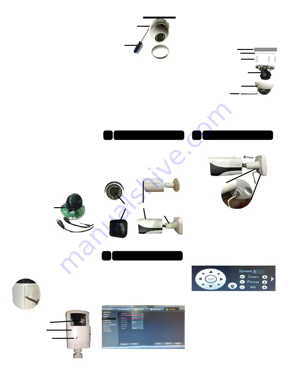
After connecting the camera to the HD-CVI series DVR
go to Main Menu ->Setting->System->PTZ. You need to
set control mode as HD-CVI and the protocol as
HD-CVI. Click save button to save current setup.
On the preview interface, right click mouse and then
select PTZ; you can see an interface shown as below.
Click Iris “+” to open menu or confirm current
operation. Click up/down button to view all the items
on the left pane of the following list. Click left/right
button to set the corresponding values on the right pane
of the following list. If there is , click confirm
button to go to the 2nd menu. Repeat the previous steps
to set detailed value. Click return button to go back to
the previous menu interface.


