CQ7-A30
CQ7-A30 - Rev. First Edition: 1.0 - Last Edition: 2.0 - Author: S.B. - Reviewed by G.G. Copyright © 2016 SECO S.r.l.
59
3.3.20
SPI Pin header
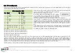
It is possible to use SPI interface, coming out from Qseven
®
card edge
connector, for the connection of external SPI Devices (like EEPROM or Flash
devices, but any kind of SPI device can be connected).
For this purpose, it is available a dual row, 10 pin, P2.54mm standard pin header, with the
pinout shown in the table on the left.
On this pin header is also available the General Purpose 1-Wire signal. Please be aware, to
avoid malfunctioning, that this signal is available only when JP5 jumper is set in position 1-2
(please check par.3.3.3)
3.3.21
SPI Flash socket
For the cases when an external Flash is needed, on the carrier board it is provided
an 8-pin SOIC socket for the housing of SPI Flashes.
Socket is type LOTES p/n ACA-SPI-004-K0 or equivalent, p. 1.27mm, with the
pinout shown in the table on the left.
Almost all signals on this socket come directly from Qseven
®
Card Edge connector, with the
following exceptions:
SPI_WP#: this signal is tied, through a 4k7
Ω
resistor, to +3.3V power rail. This means that when
the Flash is powered, the protection from writing is automatically removed.
SPI_HOLD#: this signal too is tied, through a 4k7
Ω
resistor, to +3.3V_S power rail. This means that when the Flash is powered, the Hold condition of serial
communication is automatically removed.
SPI Pin Header - CN7
Pin Signal
Pin Signal
1
+3.3V_S
2
+3.3V_S
3
SPI_CS0#
4
SPI_MOSI
5
SPI_CS1#
6
SPI_MISO
7
1-Wire_Bus
8
SPI_CLK
9
GND
10
GND
SPI Flash socket - CN6
Pin Signal
Pin Signal
1
SPI_CS0#
8
+3.3V_S
2
SPI_MISO
7
SPI_HOLD#
3
SPI_WP#
6
SPI_CLK
4
GND
5
SPI_MOSI


