SECO-LARM Surface-Mount Electric Rim Strikes
SECO-LARM U.S.A., Inc.
3
Installation:
1.
Set either fail-safe or fail-secure operation. See "Selecting
Fail-Safe/Fail-Secure," below.
2.
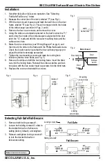
Measure the center line of the latch, labeled "Y" (see Fig.1).
3.
With the door closed, measure and mark the latch line on the door
frame, labeled "X" (see Fig. 2). This will correspond with the inside
of the strike keeper as shown in Figs. 3 and 4.
4.
Remove the four cover screws, and remove the cover.
5.
Using the strike as a template centered on the latch center line "Y,"
and so that the inside of the strike keeper is aligned with the door
latch line "X," mark and drill the two outer mounting holes and the
cable access hole.
6.
Make the wire connections (see "Wiring Diagram" on pg. 4) and
then mount the strike to the frame with the Philips flat-head screws.
Check the location and ensure that the door latches properly and
adjust the strike horizontally as needed.
7.
Tighten the two mounting screws and mark the locking hole
locations (the two inner holes, see Fig. 5).
8.
Remove the strike and drill the two locking holes. Insert the blind
nuts into the locking holes. Reinstall the strike as before and lock
into place with the hex socket head cap screws into the blind nuts.
9.
Replace the cover and reinstall the screws.
Fig. 5
Mounting
screw holes
6
3
/
8
"
(162mm)
8
1
/
4
"
(210mm)
Locking
screw holes
Latch
Center line
Y
Fig. 1
Fig. 3
Door closed
Fig. 2
Door
X
Door
frame
Door latch line
Pullman
Latch
Inside of
strike
keeper
Fig. 4
Fail-Secure:
#1
#1
#2
#2
Locking screw #1
Fail-Safe:
Sliding screw #2
#1
#2
#1
#2
Note:
SD-998C-D3AQ shown.
1.
Remove both locking screws #1.
2.
Loosen both sliding screws #2, slide to
the desired fail-safe or fail-secure
setting (factory default), and retighten.
3.
Reinsert and tighten locking screws #1
to lock the desired fail-safe or
fail-secure setting.
Selecting Fail-Safe/Fail-Secure:


