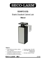
SECO-LARM Electric Deadbolt Cabinet Lock
SECO-LARM U.S.A., Inc.
3
Fig.2
Fig.3
Fig.4
Fig.1
1.
Remove the 2 holding screws from the back of the lock
body (fig.1).
2.
Remove the lock body and the wires from the solenoid.
3.
Reverse the solenoid direction (fig.2) to either match the
proper fail-safe (fig.3) or fail-secure position (fig.4).
4.
Put the wires back through the access hole.
5.
Replace the screws.
Selecting Fail-safe/Fail-secure Operation:
Fail-safe
Position
Fail-secure
Position
Installation:
1.
Set the cabinet lock to either fail-safe or fail-secure by removing the solenoid and reversing its
direction if needed (see "Selecting Fail-safe/Fail-secure Operation" above).
2.
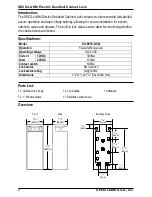
Mount the cabinet lock body. For positioning of mounting holes, refer to "Overview" dimensions
and diagrams (page 2).
3.
Determine the location of the lock plate, ensuring that the hole in the lock plate aligns with the
deadbolt. Install the lock plate with 2 included screws. Check alignment and adjust if necessary.
4.
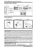
For wiring instructions, see "Wiring Connections and Diagram" (page 4).
5.
Remove the tape cover and apply the stainless steel cover onto the adhesive tape (Ensure that
the cover is clean and free of oil or dirt before applying).
Lock status
sensor
Stainless
steel cover
Lock plate
Lock body
Tape cover


