background image

SECO-LARM Electric Door Strike with Vertical Adjustment


6


SECO-LARM U.S.A., Inc.


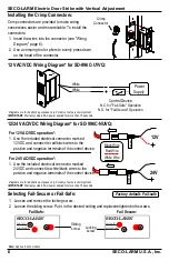
12V
D

C


12V


1.


Use the included electrical connector marked 

24VDC and connect its white/black wires to the 

positive and negative terminals of the control device. 

1.


Use the included electrical connector marked  

12VDC and connect its red/black wires to the 

positive and negative terminals of the control device. 

For 24 VAC/VDC operation*: 

For 12 VAC/VDC operation*: 

Black Wire 

Red Wire 

White Wire 

24V
D

C


24V


Crimp connectors are provided to make wiring 

connections easier and more reliable. To install the 

connectors: 

1.


Insert the wires into the connector (see "Wiring 

Diagram," page 6). 

2.


Use a crimping tool or pliers to evenly press down 

on the head of the connector.  

12/24 VAC/VDC Wiring Diagram* for SD-996C-NUVQ: 


FAIL-SECURE

FAIL-SAFE

SECO-LARM

®

*

Diagrams are for illustrative purposes only. Polarity of wires is not important. 

IMPORTANT: Warranty voided if AC power applied for more than 15 seconds.


FAIL-SECURE

FAIL-SAFE

SECO-LARM

®

Installing the Crimp Connectors: 

Note: Applies to both models 

Crimp  

Connector 

12 VAC/VDC Wiring Diagram* for SD-996C-U1VQ: 

White 

White 

Power 

Supply 

Control Device 

N.C. for "Fail-Safe" Operation 

N.O. for "Fail-Secure" Operation 

Factory default: Fail-safe 

Selecting Fail-Secure or Fail-Safe: 

1.


Loosen and remove the locking screw. 

2.


Loosen the sliding screw. Put it in the desired setting and replace/retighten both screws. 


Fail Safe: 

Fail Secure: 

Locking 

screw 

Sliding 

screw 

*

Diagrams are for illustrative purposes only. Polarity of wires is not important. 

IMPORTANT: Warranty voided if AC power applied for more than 15 seconds.
 

Содержание SD-996C-U1VQ

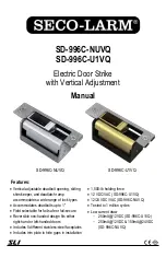
Страница 1: ...12VDC 150mA 24VDC SD 996C NUVQ Vertical adjustable deadbolt opening sliding shim keeper and deadlatch ramp accommodates a wide range of lock types Accommodates deadbolts up to 1 Field selectable for f...

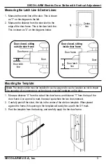
Страница 2: ...s pre cut for a strike skip to step 6 2 Measure and mark the door latch line and the center line of the door See Measuring the Latch Line Center Lines page 3 3 Apply the included stick on template to...

Страница 3: ...distance X from the side of the door frame and distance Y from the top of the door frame Use a pencil to mark the exact spot where the two lines intersect 2 Carefully peel off the short thin tab in t...

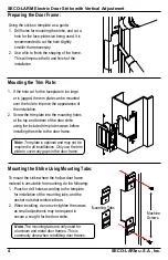
Страница 4: ...g the stick on template as a guide 1 Drill holes for mounting the strike and cut a hole for the face plate size being used It is recommended to cut the hole slightly smaller than necessary 2 Use a fil...

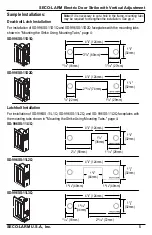
Страница 5: ...11D2Q faceplates with the mounting tabs shown in Mounting the Strike Using Mounting Tabs page 4 SD 996SS 11L1Q Note If it is necessary to cut a hole in the frame mounting tabs may be required to stre...

Страница 6: ...on the head of the connector 12 24 VAC VDC Wiring Diagram for SD 996C NUVQ FAIL SECURE FAIL SAFE SECO LARM Diagrams are for illustrative purposes only Polarity of wires is not important IMPORTANT War...

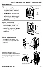
Страница 7: ...d adjust the deadbolt keeper up and down to align with the marked lines Adjusting Deadbolt Keeper 1 Move the door close to the strike and mark the deadlatch limit lines on the strike keeper when they...

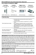
Страница 8: ...ecifications without notice SECO LARM is not responsible for misprints Trademarks are the property of SECO LARM U S A Inc or their respective owners Copyright 2016 SECO LARM U S A Inc All rights reser...

Отзывы: