


10
30" GAS SLIDE-IN RANGE INSTALLATION INSTRUCTIONS
(Models with Sealed Top Burners)
Figure 7
9.
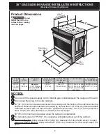
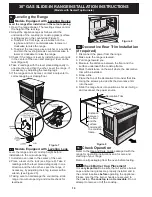
Leveling the Range
9.1
Models Equipped with Leveling Device
Level the range after installation in the cutout opening.
1. Open the range drawer. The leveling screws control
the height of the rear leg.
2. Adjust the appliance legs as follows until the
underside of the cooktop (or cooktop glass) surface
is sitting level on the countertop (Figure 7).
a. To adjust the front legs, use a wrench on the
leg base and turn counterclockwise to lower or
clockwise to raise the range.
b. To adjust the rear legs, use a ratchet or a nutdriver
and turn the leveling screws counterclockwise to
lower or clockwise to raise the range.
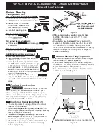
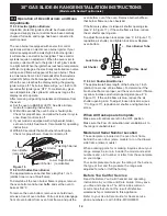
3. Check if the range is level by installing an oven rack
in the center of the oven and placing a level on the
rack (Figure 8).
4. Take 2 readings with the level placed diagonally in
one direction and then the other. Level the range, if
necessary, by adjusting the leveling legs.
5. If the range cannot be level, contact a carpenter to
correct sagging or sloping floor.
9.2
Models Equipped with Leveling Legs
Level the range and set cooktop height before
installation in the cut-out opening.
1. Install an oven rack in the center of the oven.
2. Place a level on the rack (see Figure 8). Take 2
readings with the level placed diagonally in one
direction and then the other. Level the range, if
necessary, by adjusting the 4 leg levelers with a
wrench (see Figure 23).
3. Taking care to not damage the countertop, slide
range into cutout opening and double check for
levelness.
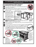
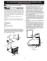
10.
Decorative Rear Trim Installation
(if required)
1. Disconnect the power from the range.
2. Make sure the range is leveled.
3. Pull range toward you.
4. Measure the distance between the floor and the
surface underneath the cooktop frame.
5. Mark that distance on the wall where the decorative
trim will be installed.
6. Draw a line.
7. Place the top of the decorative trim under that line.
8. Using the screws provided fix the decorative trim
into the wall.
9. Slide the range back into position as far as it will go
and reconnect the power source.
Figure 9
Decorative Trim
Screw (3)
Distance
between
the floor
and the
surface
underneath
the cooktop
frame.
11.
Check Operation
Refer to the Use and Care Guide packaged with the
range for operating instructions and for care and
cleaning of your range.
Remove all packaging from the oven before testing.
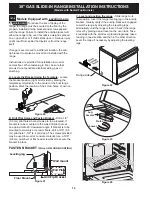
11.1
Check Burner Cap Placement
It is
very important
to be sure that all surface burner
caps and burner grates are properly installed and in
the correct locations
before
operating the appliance.
Please note that the burner heads are secured to
the cooktop.
The cooktop is not removable
. Do not
attempt to remove or lift the cooktop.
Figure 8
Содержание 30" GAS SLIDE-IN RANGE
Страница 44: ...44 NOTES NOTAS...


