


WMP-SERIES INSTRUCTIONS
Seametrics • 253.872.0284
Page 2
seametrics.com
GENERAL INFORMATION
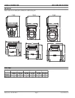
The WMP-Series meters are full-bore, plastic-bodied
electromagnetic flow meters designed for flow and usage
monitoring applications in 1, 2, and 3 inch pipe. The
polypropylene flow tube offers corrosion resistance to
a wide range of chemicals. It’s light weight and easy to
install or remove from the pipe for inspection.
With no moving parts, the magmeter permits unobstructed
flow, minimizing flow disturbances and hence, straight
pipe requirements. The WMP-Series can be used in piping
configurations where there is little space between the
meter and an elbow or valve. The WMP-Series meters are
resistant to wear from sand and debris found in ground
or surface water. Since there are no bearings or propeller
to wear out, downtime, maintenance, and repair costs are
kept to a minimum. Because there are no mechanical parts
in the flow stream, the meter tolerates high flows without
damage.
The hinged, opaque polyethylene cover protects from dust
and UV rays, while permitting easy access to the LCD flow
rate and total display. The electronics housing is made of
rugged powder-coated diecast aluminum. It can be fitted
with cross-drilled screws and seal wire for tamper-evidence.
Flow rate and total can be displayed in a variety of units,
customer-selected and factory-set.
The
WMP101
is externally powered via a 5-pin connector
and the power cable also provides pulse output for use with
a variety of Seametrics and other displays and controls for
remote reading, data logging, pulse-to-analog conversion,
and telemetry applications.
The
WMP104
is a battery-operated unit for use when pulse
output is not required. The standard batteries are user
replaceable with an approximate 1–2 year life depending on
usage. An extended battery life option offers an estimated
2–4 year life depending on usage.
In the event of DC power loss, or when changing the
battery, the WMP is designed to retain the internal settings
and flow total.
General Information
General Information
...................................................................................................................................................Page 2
Features ...........................................................................................................................................................................Page 3
Specifications
................................................................................................................................................................Page 3
Dimensions
....................................................................................................................................................................Page 4
Flow Range
.....................................................................................................................................................................Page 4
Installation
Piping Conditions
........................................................................................................................................................Page 5
End Connections
..........................................................................................................................................................Page 5
Positioning......................................................................................................................................................................Page 5
Straight Pipe Recommendations
...........................................................................................................................Page 6
Full Pipe Recommendations
....................................................................................................................................Page 6
Connections and Operation
Electrical Connections
................................................................................................................................................Page 7
Cable Connections
......................................................................................................................................................Page 7
Grounding ......................................................................................................................................................................Page 7
Operation ........................................................................................................................................................................Page 7
Maintenance and Troubleshooting
Maintenance ..................................................................................................................................................................Back
Troubleshooting ...........................................................................................................................................................Back


