


CT2X INSTRUCTIONS
Seametrics • 253.872.0284
Page 16 inwusa.com
OPERATION/DIRECT READ MODBUS & SDI-12
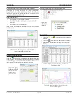
Exporting Data to .csv or .xls Files*
• Click the or tool button to view data as
a table.
• Click on the tool button.
•
Select a file location and enter a name for the file.
•
Select a file type.
• Click Save.
* When using Windows 10, files can only be exported in .csv format. They
can then be opened manually from Excel or any other spreadsheet or
database program
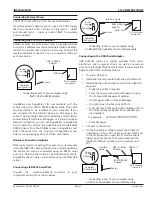
A Word About Units
Readings from the CT2X Smart Sensor can be displayed in
various units, such as PSI, Ft. H2O, or mm H2O for pressure,
or degrees Celsius or degrees Fahrenheit for temperature.
Select the units you want from the Options | Display Units
menu or from the Configure Menu | Program Configuration
| Set Computer Display Units.
DIRECT READ (MODBUS
®
OR SDI-12)
While the CT2X comes with INW’s easy to use Aqua4Plus
or Aqua4Plus Lite software, you can also use standard
Modbus
®
RTU or SDI-12 equipment to easily take readings,
so as to tie into your existing equipment or networks.
You may need to use Aqua4Plus/Aqua4Plus Lite to make
a few settings prior to directly reading the CT2X with your
equipment. These might include the units for the returned
values and/or the Modbus baud rate. These are described
in the following sections.
For Modbus direct read, you must have CT2X firmware 1.5
or higher. For SDI-12, you must have firmware 2.0 or higher.
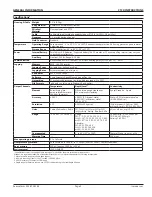
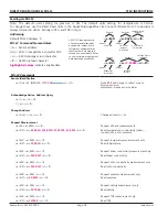
Setting Units for Direct Read
By default, the CT2X uses the following units:
Temperature Degrees Celsius
Conductivity µS/cm
Pressure PSI
Salinity PSU*
TDS mg/L*
*Firmware version 2.8 or higher
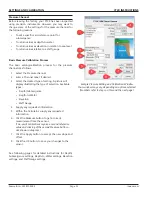
If you have firmware 2.2 or later, you can select from a
variety of units. If you want to change to different units,
for example, degrees Fahrenheit for temperature or meters
of water for pressure, set these units using Aqua4Plus/
Aqua4Plus Lite, as shown below. Note: Conductivity is
always returned in µS/cm, Salinity in PSU, and TDS in mg/L.
• From Aqua4Plus select Direct Read Units from the
Configure | Advanced menu.
• From Aqua4Plus Lite select Set Direct Read Units
from the Sensor configure menu.
• On the popup box, click the down-arrows next to
the channel types you want to change, and then
select the units you want.
• Click OK.
Select the units for your direct read
measurements, whether Modbus or SDI-12.
Once set, these units are saved on the sensor and direct
readings, either via Modbus or via SDI-12, will return values
using these units. (Note: These settings do not affect the
units used on the Aqua4Plus/Aqua4Plus Lite display. Refer
to the software instructions for details.)


