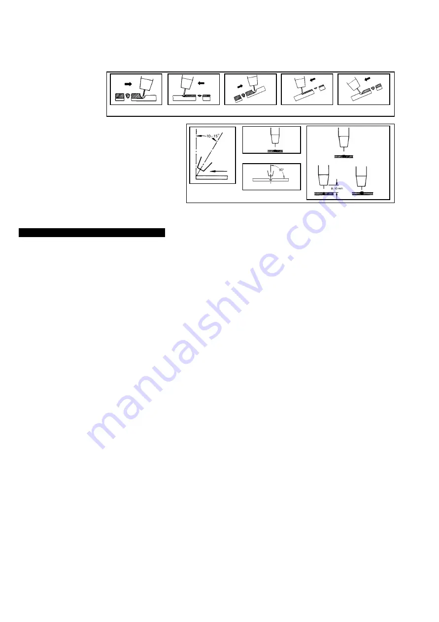
4.8
Overview of the welding process.
IMPORTANT.
Should you have no welding experience, we recommend you seek training from an expert source to ensure your personal health & safety.
You must familiarise yourself with welding applications and limitations, and specific potential hazards peculiar to welding. Good Mig welding may be achieved only
with continued, supervised practice.
For example:
Correct torch angle and direction of
travel in relation to the workpiece is
essential for the appearance and
quality of the weld. Illustrations
demonstrate various positions and
directions.
p
p
p
WARNING! Ensure the unit is disconnected from the mains power supply before performing any maintenance or service.
5.1
Regularly check all welding cables and secondary terminals to ensure they are in good order and connected correctly, also check during welding to
ensure they are not overheating.
5.2.
Check that the gas hose connections are tight and that there are no gas leaks.
5.3.
Regularly inspect the machine interior according to the frequency of use and dust in the working area. When removing dust from transformer, choke
tap and rectifier always use dry air of not more than 10bars.
NOTE:
Care must be taken NOT to direct compressed air towards the control modules, which may be cleaned with a soft brush.
5.4.
Wire feed unit
Check the wire feed unit at regular intervals. The feed roller wire guide plays an important part in obtaining consistent results. Poor wire feeding affects
welding. Clean the rollers weekly, especially the feed roller groove, removing all dust deposits.
5.5.
Changing Feed Roller
IMPORTANT:
Adjust the feed roller to the corresponding wire size.
There are two grooves on the feed roller, one to take 0.6mm and the other 0.8mm wire. Use grove on the inside of the roller, (that is the groove
farthest from you). To remove the bottom feed roller, lift the top feed roller and undo the central screw on the bottom roller sliding it off the spindle. Clean
and turn the feed roller (or replace if damaged) then refit it by pushing it back onto the spindle, locating it on the keyway and securing in place with the
central screw.
5.6.
Torch
Protect torch cable assembly from mechanical wear. Clean liner from the machine forwards by using compressed air. If the liner is clogged it must be replaced.
5.7.
Contact Tip
(to remove tip follow steps in 3.5, depending on model).
The contact tip is a consumable item and must be replaced when the hole becomes enlarged or oval. The contact tip
MUST
be kept free from spatter to
ensure an unimpeded flow of gas.
5.8.
Gas Cup
(to remove cup follow steps in 3.5. depending on model).
The gas cup must also be kept clean and free from spatter. Build up of spatter inside the gas cup can cause a short circuit at the contact tip which will result
in either the fuse blowing on the printed circuit card, or expensive machine repairs. To keep the contact tip free from spatter, we recommend the use of Sealey
anti-spatter spray (MIG/722307) available from your Sealey Dealer.
5.9.
Changing Fuses
The fuse is located on the auxiliary transformer and is mainly blown for the following reasons:
3
Spatter collecting in the gas cup, causing contact tip to short circuit.
3
Wire tension is too great.
3
A sudden surge of current.
5. MAINTENANCE
1. Direction of
Welding
3. Fillet Weld
3. Butt Weld
Normal
Welding
Arc
Short
Welding
Arc
Long
Welding
Arc
Rightward Welding
Leftward Welding
Vertical Rightward
Downhand leftward
Down Rightward
Welding with a long arc reduces penetration and widens the arc. This
in turn results in more spatter. A long welding arc can be appropriate
for welding butt joints in thin materials. Welding with a short arc
(at the
same weld settings
) results in greater penetration and a narrower
weld and reduces the amount of spatter.
We recommend expert training and supervised practice.
POWERMIG2500, 2750, 3500, 4500. - (0051) - (1) - 270100


