


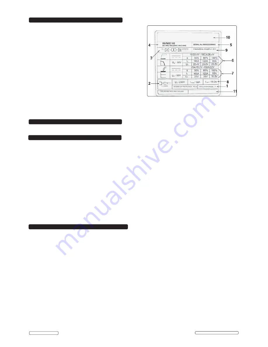
The ratings plate on the inverter gives the following data:
1 - Rating of internal protection provided by casing.
2 - Symbol for power supply line: 1= Single-phase AC.
3 - Symbol for internal structure of the welding machine.
4 - Model No.
5 - Manufacturers Serial Number for welding machine identification.
6 - MMA Output.
7- MIG
Output
Uº: Maximum no load voltage.
I
²
, U
²
: Current and corresponding normalised voltage that the
welding machine can supply during welding.
X: Welding ratio based on a 10 minute duty cycle. 30% indicates 3
minutes welding and 7 minutes rest, 100% indicates continuous welding.
A/V-A/V: Shows the range of adjustment for the welding current
(minimum - maximum) at the corresponding arc voltage.
8 - Power Supply
U
1
: Alternating voltage and power supply frequency of welding machine.
(allowed limit ± 10%)
I
1
max
: Maximum current absorbed by the line.
I
1
eff
: Effective current supplied.
9 - The EUROPEAN standard relating to the safety and construction
of arc welding machines.
10 - Manufacturer's details.
11 - Safety regulation symbols shown here.
8. RATINGS
PLATE
10.1.
WIRE FEED UNIT
Check the wire feed unit at regular intervals. The feed roller wire guide plays an important part in obtaining
consistent results. Poor wire feed affects welding. Clean the rollers weekly, especially the feed roller groove, removing all dust
deposits.
10.2. TORCH
Protect the torch cable assembly from mechanical wear. Clean the liner from the machine forwards by using compressed air.
If the liner is clogged it must be replaced.
10.3. CHANGING FEED ROLLER
(See Section 3.7)
10.4. CONTACT TIP
The contact tip is a consumable item and must be replaced when the hole becomes enlarged or oval. The contact tip
MUST
be kept free from spatter to ensure an unimpeded flow of gas. Refer to fig.8 and section 3.5.4 for removal and replacement.
10.5. GAS CUP
The gas cup must also be kept clean and free from spatter. Build up of spatter inside the gas cup can cause a short circuit
at the contact tip which will result in either the fuse blowing on the printed circuit card, or expensive machine repairs. To keep the
contact tip free from spatter, we recommend the use of Sealey anti-spatter spray (MIG/722308) available from your Sealey Dealer.
Refer to fig.8 and section 3.5.4 for removal and replacement.
10.6. REPLACING THE LINER
Wind the wire back on to the spool and secure it. Unscrew the torch from the machine and undo the brass
nut. The liner should now be visible. Pull it out and replace with a new one.
10.7
Remove the casing periodically and, with a low pressure air flow (max 1bar or 15psi),remove dust from inside the machine.
10.8.
Do not direct compressed air onto the electronic circuit boards, these should be cleaned with a very soft brush.
10.9.
Ensure that all electrical connections are tight and check the wiring for damage to the insulation.
10.10.
Ensure that the casing is correctly replaced and secured before attempting to use the inverter.
10.11.
Keep the outside of the machine clean by wiping with a soft, dry cloth.
For any other service or maintenance, contact your local Sealey service agent.
9. DUTY CYCLE
10. MAINTENANCE
11. ELECTROMAGNETIC COMPATIBILITY
11.1.
THIS EQUIPMENT IS IN CONFORMITY WITH THE EUROPEAN STANDARD ON THE ELECTROMAGNETIC COMPATIBILITY
OF ARC WELDING EQUIPMENT AND SIMILAR PROCESSES (e.g. ARC AND PLASMA CUTTING)
11.2.
Protection against interference. (E.M.C.)
The emission limits in this standard may not, however, provide full protection against
interference to radio and television reception when the equipment is used closer than 30m to the receiving antenna. In special cases,
when highly susceptible apparatus is being used in close proximity, additional mitigation measures may have to be employed in order
to reduce the electromagnetic emissions. At the same time there could occur some potential difficulties in having electromagnetic
compatibility in a non-industrial environment (e.g. in residential areas). Therefore it is most important that the equipment is used and
installed according to the following instructions.
11.3.
Installation and use.
The user is responsible for installing and using the equipment according to these instructions. If electromagnetic
disturbances are detected, then it shall be the responsibility of the user of the equipment to resolve the situation with the technical
assistance of the supplier. In some cases this remedial action may be as simple as earthing the circuit (see Note). In other cases it
could involve constructing an electromagnetic screen, enclosing the welding power source and the work, complete with associated
input filters. In all cases the electromagnetic disturbances shall be reduced to the point where they are no longer troublesome.
Note: The welding/cutting circuit may or may not be earthed for safety reasons. Changing the earthing arrangements should only be
authorised by a person who is competent to assess whether the changes will increase the risk of injury, e.g. by allowing parallel
welding/cutting circuit return paths which may damage the earth circuits of other equipment. Further guidance is given in IEC 974-13
'Arc Welding Equipment - Installation and Use.’
11.4.
Assessment of area.
Before installing the equipment the user shall make an assessment of potential electromechanical problems in
the surrounding area. The size of the surrounding area to be considered will depend on the structure of the building and other activities
that are taking place. The surrounding area may extend beyond the boundaries of the premises.
The following shall be taken into account :
a) Other supply cables, control cables, signalling and telephone cables, above, below and adjacent to the welding equipment.
b) Radio and television transmitters and receivers.
c) Computer and other control equipment.
Original Language Version
© Jack Sealey Limited
When the machine reaches the end of its duty cycle and overheats, the thermostatic switch opens to allow the internal components
to cool. This is denoted by the yellow LED (
fi
g 1.4) illuminating. Allow the machine to cool and resume use when the light goes out.
INVMIG160 | Issue: 2S - 08/01/15


