fig 5.2.
5. 2. HBS Brake System.
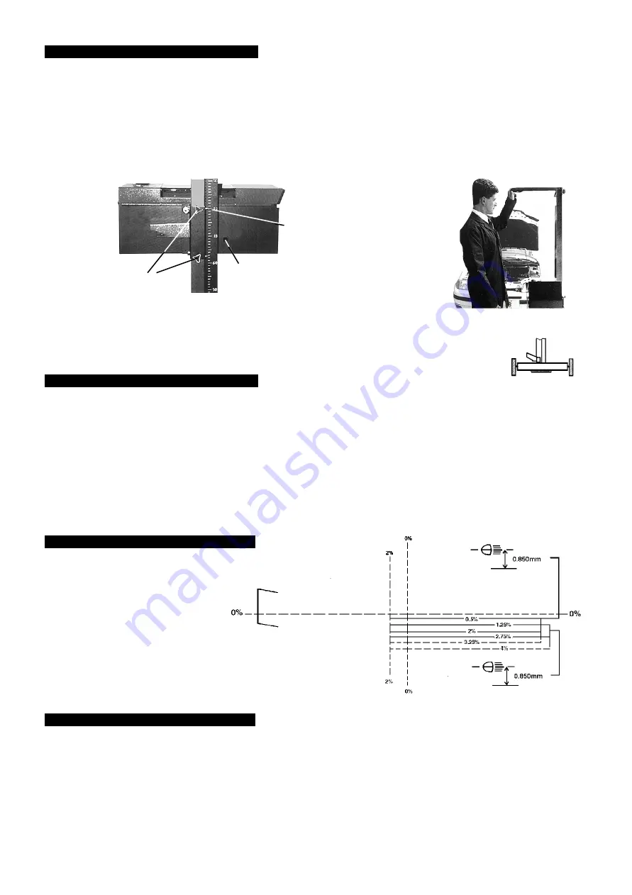
The HBS system is fitted with a rotating column and is suitable for use either on or off rails.
If you are using the system on rails then the rotating column aids correct alignment. To release
the column brake (fig 5.2.) put pressure on release mechanism. To apply column brake,
put pressure on foot pedal.
6. 1. Switch engine on.
6. 2 Align the headlamp aim equipment with the longitudinal axis of the vehicle.
6. 3. Align the centre of the collecting lens with the centre of the headlamp under test.
6. 4. With an assistant sitting in the driving seat, switch on the headlamps to the beam on which the headlamp is to be checked.
Note:
When checking headlamp aim on vehicles with hydropneumatic suspension systems, it is necessary to have the engine idling.
6. 5. Determine the appropriate headlamp beam image and its aim (See fig 7A.). Old vehicles (approx. pre 1950 ) headlamps beam image
may not conform to fig 7A, in such cases check::
a)
DIP BEAM
headlamps are aimed so they do not dazzle =, ie the beam image brightest part is aimed at least 0.5% below
the horizontal (fig 8A). Or, for headlamps which cannot be checked on dip beam, check:
b)
MAIN BEAM
headlamps are aimed so that the beam image centre is on or slightly below the horizontal (fig 9A).
5.1.
Positioning.
Locate the HBS approximately 200 to 500mm from the vehicles headlight.
5. 1. 1 Use the visor to align with a horizontal, or two symmetrical points on the vehicle fig 5B. i.e. The bonnet lip or the bottom
of the windscreen.
5. 1. 2. Ensure the visor lines match with your horizontal, or symmetrical selection, to ensure the HBS is parallel to the headlamp.
5. 1. 3. Using the scale situated on the carrier (fig 5A.) measure the height from the floor to the centre of the headlight. As a point
of reference, you must use the top of the Vertical sliding system or VSS.
e.g. The height from floor is 650mm, place the VSS at the 650mm mark as shown in (fig 5A.). There is a tolerance level of 30mm.
Locking Screws
manoeuvre
here
650mm
fig 5A.
fig 5B.
Level
Adjustment
5. OPTICAL POSITIONING
6. METHOD OF INSPECTION
CORRECT LIGHT PROJECTION ON THE LINE 0.5% (BEAM LIGHT)
fig 7A
7. GRADUATED SCREEN
IMPORTANT
The HBS system uses a fixed graduated
screen in accordance with the requirements
of the MOT regulations.
8. DIPPED BEAM
8. 1. Prepare the HBS , and the car as previously instructed, then turn on the dipped beam.
8. 2. Check the headlamp beam tolerances are in accordance with MOT inspection manual, and are within operating tolerances
of manufacturers guidelines.
8. 3. Adjust the vehicles light regulating system until you obtain the required result.
8. 4. When testing the more commonly used asymmetrical headlight (see fig 7A), remember that their projection will light up a section
on the
LEFT
hand side of the plate with a corner of about 15
0
from the horizontal plane. Just under the centre, on the right, a small
zone will appear brighter than the rest of the projection.
HBS97HBS971- 165 - 240498


