background image

INSTRUCTIONS FOR 

ELECTROSPOT 8000

ELECTROSPOT 9500.V2

Thank you for purchasing a Sealey ElectroSpot welder. Manufactured to a high standard this product will, if used according to these instructions
and properly maintained, give you years of trouble free performance.

IMPORTANT

BEFORE USING THIS PRODUCT, PLEASE READ THE INSTRUCTIONS CAREFULLY. NOTE THE SAFE OPERATIONAL

REQUIREMENTS, WARNINGS, AND CAUTIONS. USE THIS PRODUCT CORRECTLY, AND WITH CARE, FOR THE PURPOSE FOR WHICH
IT IS INTENDED. FAILURE TO DO SO MAY CAUSE DAMAGE AND/OR PERSONAL INJURY AND WILL INVALIDATE THE WARRANTY.

1.

SAFETY INSTRUCTIONS

1.1. ELECTRICAL SAFETY

WARNING! 

ELECTRICAL INSTALLATION OF SPOT WELDER TO  A 3 PHASE 415VOLT SUPPLY MUST ONLY BE CARRIED OUT BY A

QUALIFIED ELECTRICIAN. Make sure that the power supply cable is correctly connected to the Earth. It is the user’s responsibility to
read, understand and comply with the following:

You must check all electrical equipment and appliances to ensure that they are safe before using. You must inspect power supply leads, plugs
and all electrical connections for wear and damage. You must ensure the risk of electric shock is minimised by the installation of appropriate
safety devices. An RCCB (Residual Current Circuit Breaker) should be incorporated in the main distribution board. 

You must

also read and understand the following instructions concerning electrical safety.

1.1.1. The 

Electricity At Work Act 1989

requires all portable electrical appliances, if used on business premises, to be tested by 

a qualified electrician, using a Portable Appliance Tester (PAT), at least once a year.

1.1.2. The 

Health & Safety at Work Act 1974

makes owners of electrical appliances responsible for the safe condition of the appliance 

and the safety of the appliance operator. 

If in any doubt about electrical safety, contact a qualified electrician.

1.1.3. Ensure that the insulation on all cables and the product itself is safe before connecting to mains power supply.
1.1.4. Ensure that cables are always protected against short circuit and overload.
1.1.5. Regularly inspect power supply, leads, plugs and all electrical connections for wear and damage, 

and especially power connections, to ensure that none is loose. 

1.1.6.

Important:

Ensure that the voltage marked on the product is the same as the power supply

to be used. A three phase plug must be fitted to this machine.

1.1.7. DO NOT pull or carry the appliance by any of the input or output cables. 
1.1.8. DO NOT pull power plugs from sockets by the power cable.
1.1.9. DO NOT use worn or damage leads, plugs or connections. Immediately replace or have repaired by 

a qualified electrician. 

1.1.10. DO NOT use this product with a cable extension reel

.

1.1.11.

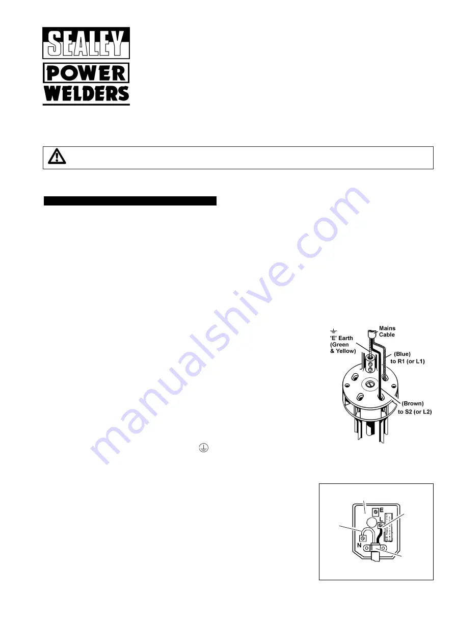
THE SPOT WELDER HAS A ‘SINGLE PHASE CABLE’ BUT MUST BE CONNECTED 
TO A THREE PHASE SUPPLY.                                      

This product must be fitted with a 3 phase plug according to this diagram, and will 
require a 32 amp per phase supply. You must contact a qualified electrician to ensure that 
an appropriately fused supply is available. 

Connect GREEN/YELLOW wire to Earth (E or 

) terminal.

Connect BLUE wire to R1 (or L1) terminal.
Connect BROWN wire to S2 (or L2) terminal.

Note that both brown 

and blue

wires will be ‘live’ when the plug is connected to the supply.

Finally, check that there are no bare wires, that all wires have been connected correctly, that the cable external insulation extends
beyond the cable restraint and that the restraint is tight.

1.1.12. The water cooler (ElectroSpot 9500 only) will require a BS 1363/A 3 pin plug to be fitted 

as follows (UK only):

a) Connect the GREEN/YELLOW earth wire to the earth terminal ‘E’.
b) Connect the BROWN live wire to the live terminal ‘L’.
c) Connect the BLUE neutral wire to the neutral terminal ‘N’.
d) After wiring, check that there are no bare wires, that all wires have been correctly 

connected, that the cable outer insulation extends beyond the cable restraint and
that the restraint is tight.

e) Fit a fuse, rated as shown on the right, to the plug.

FUSE RATING 5 AMP

Blue
Neutral 
Wire

Yellow & Green 
Earth Wire 

Cable 
Restraint

Brown
Live 
Wire

ElectroSpot 8000/9500.V2 - 2 - 040903

Содержание ELECTROSPOT 8000

Страница 1: ...Models ElectroSpot 8000 9500 V2 2 040903 ELECTROSPOT 9500 V2 ELECTROSPOT 8000 ELECTROSPOT 9500 V2 INSTRUCTIONS FOR SPOT W WELDERS ...

Страница 2: ...cting to mains power supply 1 1 4 Ensure that cables are always protected against short circuit and overload 1 1 5 Regularly inspect power supply leads plugs and all electrical connections for wear and damage and especially power connections to ensure that none is loose 1 1 6 Important Ensure that the voltage marked on the product is the same as the power supply to be used A three phase plug must ...

Страница 3: ...othing to protect yourself from sparks and hot droplets of fused metal Cover exposed flesh to avoid burns DO NOT operate the welder if it or the cables are damaged DO NOT hold or touch the pieces to be welded All workpieces must be suitably clamped DO NOT place your hands near the electrodes danger of burning and or crushing The operator must be fully trained in the use of the welder and must be a...

Страница 4: ...ure that the air valve is in the off position before connecting to the air supply 4 2 The pneumatic clamps require a compressed air supply of 6 to 8 bar connected to the filter regulator at the rear of the welder 4 3 WARNING Ensure that the air supply does not exceed 8 bar while operating the welder Too high an air pressure and or unclean air will shorten the product life due to excessive wear and...

Страница 5: ...ND CABLE CONNECTION fig 3 6 3 1 Connect the two Dinse plugs into the welder sockets 6 3 2 Plug in control cable 6 4 AIR PULLER GROUND CABLE CONNECTION fig 4 6 4 1 Connect the two Dinse plugs into the welder sockets 6 4 2 Plug in air line from puller to welder air outlet and connect control cable 7 FRONT PANEL ELECTROSPOT 8000 fig 2 fig 5 The following describes the functions of the front panel key...

Страница 6: ... two Dinse adaptors to the welder output plates 8 4 2 Plug the Dinse plugs into the adaptors and connect the control cable 8 5 AIR PULLER GROUND CABLE CONNECTION fig 9 8 5 1 Connect the two Dinse adaptors to the welder output plates 8 5 2 Connect the two Dinse plugs into the adaptors 8 5 3 Plug air line from puller into welder air outlet and connect control cable 8 6 DOUBLE SPOT CLAMP CONNECTION P...

Страница 7: ...The lower arm should be inserted fully into its socket and secured with the two grub screws provided Adjust the upward protrusion of the short electrode to 22mm and ensure that it is vertical The upper arm and electrode should then be adjusted so that the electrodes are vertically aligned when viewed from the front and so that the tips coincide when the clamp closes When at rest the distance betwe...

Страница 8: ...ng current for a pre set time Welding is indicated by the green LED Release the clamp lever a few moments after the LED goes out This delay in releasing the clamp load improves the mechanical strength of the weld Operate the pneumatic clamp with a regulated air supply of 4 to 8 bar 10 2 4 HOW TO USE THE STUDDER To assemble or disassemble electrodes use two hex wrenches one to prevent the clamp spi...

Страница 9: ...p push button and keep it pressed Move the electrode during each pause in the weld pause cycle provided by the machine The work pause cycles are controlled automatically by the spot welder according to sheet thickness Keep a light pressure on the electrode 3 4kg and weld along a line ideally 2 3mm in from the edge of the new piece To achieve good results DO NOT weld more than 300mm from ground poi...

Страница 10: ...20 132299 Mains Cable 2 5mm2 x 4m 12 120 990598 Auxiliary Transformer 13 120 169209 Transformer 400V ITEM PART NO DESCRIPTION 14 120 313551 Front Panel Card 15 120 322472 Front Panel 16 120 649338 Bottom 17 120 655232 Cover 18 120 712037 Dinse Socket DX 70 95 19 120 602022 Manometer 20 120 602071 Air Regulator 21 120 602086 Glass for Regulator 22 120 990046 Bushing Nut Cable 23 120 602116 Quick Co...

Страница 11: ... 7 120 432382 FIXED ELECTRODE HOLDER 8 120 432383 MOBILE ELECTRODE HOLDER 9 120 483220 PIN 10 120 483221 PIN ITEM PART NO DESCRIPTION 11 120 483278 BLOCK CABLE 12 120 602157 CYLINDER D 50 13 120 644913 PLATE 14 120 483222 LEVER 15 120 690005 ELECTRODE HOLDER ARM L 120MM 16 120 690047 STRAIGHT ELECTRODE L 130MM D 12MM 17 120 690050 STRAIGHT ELECTRODE L 50MM D 12MM 18 120 713066 CLAMP CABLE 19 120 8...

Страница 12: ...5 120 482774 Pin 36 120 602121 Cylinder ITEM PART NO DESCRIPTION 37 120 631010 Pneumatic Clamp Movable Head 38 120 690005 Electrode Holder Arm 120mm 39 120 690047 Straight Electrode 130mm x Ø12mm 40 120 690050 Straight Electrode 50mm x Ø12mm 41 120 713054 Cable 120mm2 x 2m Electrode Holder 42 120 713056 Cable 120mm2 x 2m Electrode Holder 43 120 120111 Switch Cable 44 120 803151 Straight Arms 120mm...

Страница 13: ...17 120 990168 Kit Replacing Card 18 120 322481 Front Panel 19 120 322463 Handle ITEM PART NO DESCRIPTION 20 120 322469 Upper Connector Cover 21 120 322470 Lower Connector Cover 22 120 690000 Copper Upper Bar 23 120 690002 Copper Lower Bar 24 120 602000 Quick Connect 25 120 602022 Manometer 26 120 602071 Air Regulator 27 120 602086 Glass for Air Regulator 28 120 602106 Quick Connection 29 120 60210...

Страница 14: ...er 53 120 990176 Straight Arms 250mm Electrodes 54 120 990117 Kit Jaw 55 120 990175 Air Cooling Unit Kit ITEM PART NO DESCRIPTION 56 120 990169 Bracket Kit 57 120 712049 Electrode Connection 58 120 713051 Cable 150mm2 x 0 35mm Electrode Holder 59 120 690059 Pincer Air Tube 60 120 122353 Switch Cover 60 120 122381 Switch 61 120 132335 Mains Cable 1 5mm2 x 2m 62 120 152217 Fan Blade 63 120 323001 Fo...

Страница 15: ...CIRCUIT DIAGRAMS FOR ELECTROSPOT 8000 ELECTROSPOT 9500 V2 ELECTROSPOT 8000 ELECTROSPOT 9500 V2 ELECTROSPOT 9500 COOLER Issue 2 Date Issued 040903 ...

Страница 16: ...TROLLEY ASSEMBLY DIAGRAM FOR ELECTROSPOT 8000 TROLLEY ASSEMBLY DIAGRAMS FOR ELECTROSPOT 9500 V2 Issue 2 Date Issued 100807 Issue 1 Date Issued 270602 ...

Страница 17: ......

Страница 18: ...Edmunds Suffolk 01284 757500 sales sealey co uk 01284 703534 e mail Web www sealey co uk SPOT WELDERS Models ELECTROSPOT 8000 ELECTROSPOT 9500 V2 SPOT WELDERS Models ELECTROSPOT 8000 ELECTROSPOT 9000 V2 73 23 EEC Low Voltage Directive 89 336 EEC EMC Directive 93 68 EEC Marking Directive We the sole importer into the UK declare that the products listed below are in conformity with the following sta...

Отзывы: