background image


Appendix D – Asynchronous Communications 

Serial data communications implies that individual bits of a character are transmitted consecutively to a 
receiver that  assembles the bits back into a character. Data rate, error checking, handshaking, and 
character framing (start/stop bits) are pre-defined and must correspond at both the transmitting and 
receiving ends. 

Asynchronous communications are the standard means of serial data communication for PC compatible 
and PS/2 computers. The original PC was equipped with a communication or COM port that was designed 
around an 8250 Universal Asynchronous Receiver Transmitter (UART). This device allows asynchronous 
serial data to be transferred through a simple and straightforward programming interface. A starting bit 
followed by a pre-defined number of data bits (5, 6, 7, or 8) defines character boundaries for asynchronous 
communications. The end of the character is defined by the transmission of a pre-defined number of stop 
bits (usually 1, 1.5 or 2). An extra bit used for error detection is often appended before the stop bits. The 
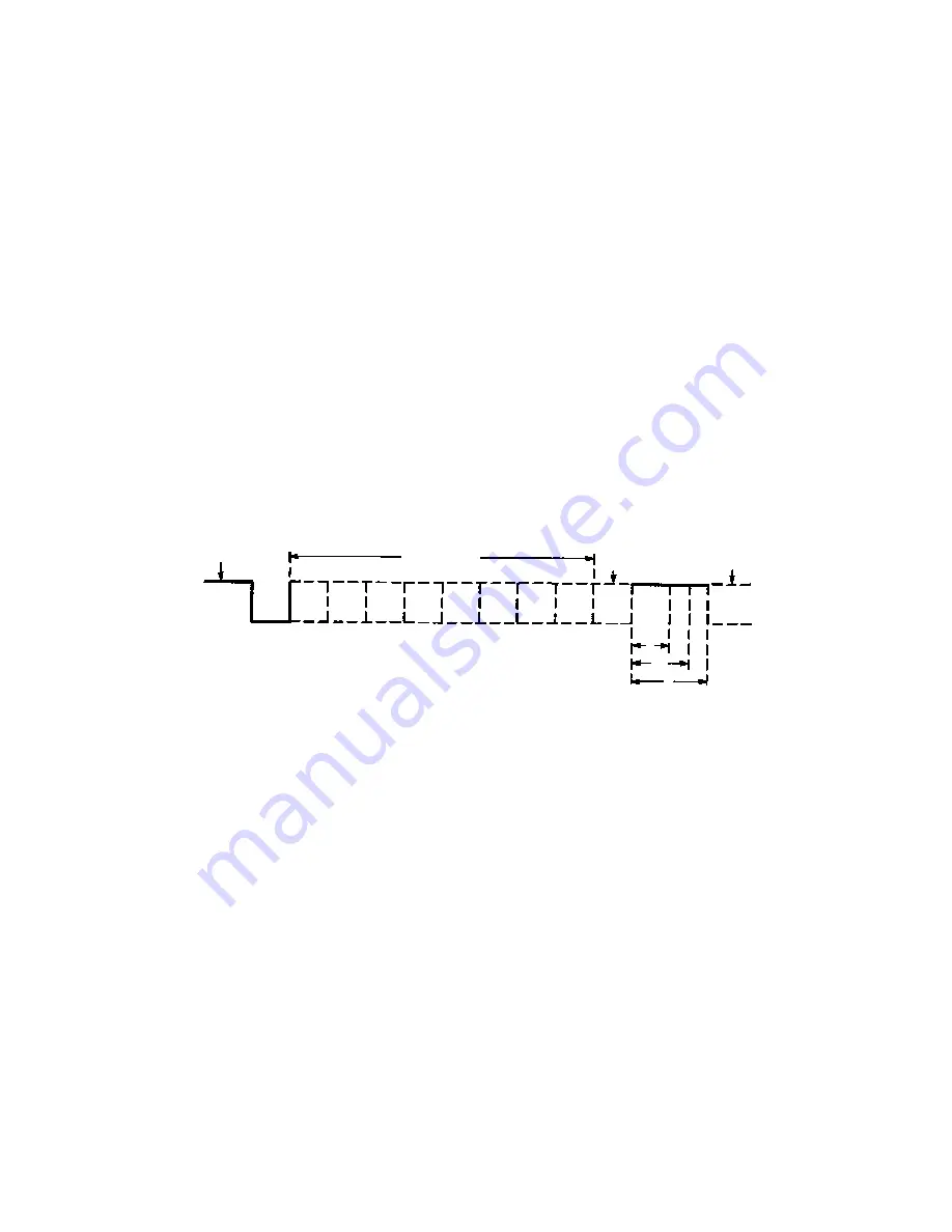
diagram below demonstrates asynchronous communication bits. 


This special bit is called the parity bit. Parity is a simple method of determining if a data bit has been lost 
or corrupted during transmission. There are several methods for implementing a parity check to guard 
against data corruption. Common methods are called (E)ven Parity or (O)dd Parity. Sometimes parity is not 
used to detect errors on the data stream. This is referred to as (N)o parity. Because each bit in 
asynchronous communications is sent consecutively, it is easy to generalize asynchronous 
communications by stating that each character is wrapped (framed) by pre-defined bits to mark the 
beginning and end of the serial transmission of the character. The data rate and communication 
parameters for asynchronous communications have to be the same at both the transmitting and receiving 
ends. The communication parameters are baud rate, parity, number of data bits per character, and stop bits 
(i.e., 9600,N,8,1). 


Remain Idle or

next start bit

Odd, Even 

      or

  Unused

STOP

 P

BIT

5 to 8 Data Bits

Idle state of

      line

1

0

1

1.5

2

Содержание 2105R

Страница 1: ...SEALINK 232 DB9 User Manual 2105R...

Страница 2: ...SPECIFICATIONS 12 HARDWARE CONFIGURATION 13 INSTALLATION 14 HARDWARE INSTALLATION 16 APPENDIX A HANDLING INSTRUCTIONS 24 APPENDIX B TROUBLESHOOTING 25 APPENDIX C ELECTRICAL INTERFACE 29 APPENDIX D AS...

Страница 3: ...isory Conventions Warning The highest level of importance used to stress a condition where damage could result to the product or the user could suffer serious injury Important The middle level of impo...

Страница 4: ...is compatible with all standard PC baud rates 300 bps and above and supports high speed communication to 921 6K bps The 2105R is powered by the USB port and status LEDs molded into the enclosure indic...

Страница 5: ...a DB25M connector on the other This cable is 72 inches in length DB9F to DB9M Extension Cable Part CA127 The CA127 allows users to extend a DB9 cable up to six feet The connectors are pinned one to o...

Страница 6: ...revent accidental removal of the power cable High Speed 7 Port USB 2 0 Hub Part Hub 7P The HUB7P is USB 2 0 compliant providing a full 480M bps data rate to the host and is backwards compatible with U...

Страница 7: ...ell chassis Convenient DB9 input and output connects directly to the protected port obtaining a ground outlet from the computer chassis Surge suppression is handled with balanced arrays of high speed...

Страница 8: ...r 2223 USB to 2 Port RS 232 RS 422 RS 485 Software Configurable DB9 Serial Interface Adapter 2201 USB to 2 Port RS 232 DB9 Serial Interface Adapter 2202 USB to 2 Port RS 422 RS 485 DB9 Serial Interfac...

Страница 9: ...USB to 1 Port RS 232 RS 422 RS 485 Software Configurable DB9 Serial Interface Adapter 2223 KT USB to 2 Port RS 232 RS 422 RS 485 Software Configurable DB9 Serial Interface Adapter 2223 OEM USB to 2 P...

Страница 10: ...USB to 4 Port RS 232 RS 485 RJ45 VersaCom Serial Interface Adapter for Powering 24VDC Serial Peripherals 2804 DC05 USB to 8 Port RS 232 RJ45 Serial Interface Adapter for Powering 5VDC Serial Periphera...

Страница 11: ...Detect Input 2 RXD Receive Data Input 3 TXD Transmit Data Output 4 DTR Data Terminal Ready Output 5 GND Ground 6 DSR Data Set Ready Input 7 RTS Request To Send Output 8 CTS Clear To Send Input 9 RI Ri...

Страница 12: ...to 221 F Humidity Range 10 to 90 R H Non Condensing 10 to 90 R H Non Condensing Power Requirements Supply line 5 VDC Rating 100 mA Manufacturing All Sealevel Systems Printed Circuit boards are built t...

Страница 13: ...re detailed in the previous Electrical Specifications section Status LEDs A pair of status LEDs indicate Tx Red Light when data is being transmitted Rx Green Light when data is being received Attached...

Страница 14: ...for the adapter from the listing 3 Select Download Now for SeaCOM for Windows 4 The setup files will automatically detect the operating environment and install the proper components Follow the inform...

Страница 15: ...ading to the current SeaCOM driver 1 Download the current driver using the Instructions from the Installation section above Please take note of the destination directory it will save to 2 Uninstall th...

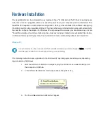
Страница 16: ...r more Found New Hardware windows indicating the actual device being created and enumerated See below In Vista and newer operating systems the enumeration occurs automatically without user interaction...

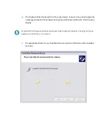
Страница 17: ...4 Choose No not this time and click Next to proceed 5 Choose Install the software automatically and click Next...

Страница 18: ...tating that the hardware has not passed Windows certification Click Continue Anyway All SeaCOM software and drivers have been fully tested by Sealevel Clicking Continue anyway will not harm your syste...

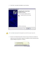
Страница 19: ...Hardware Wizard appears a second time repeat steps 4 8 9 When the Found New Hardware alert informs you that your hardware is installed and ready to use you can proceed with verifying the installation...

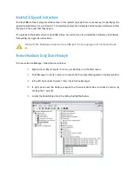
Страница 20: ...y Computer icon on your desktop or in the Start menu 2 Click Manage in the fly out menu to launch the Computer Management console window 3 In the left pane under System Tools click Device Manager 4 In...

Страница 21: ...d by the upgrade instructions Start with the hardware connected to a USB port Do not unplug it until instructed to do so Remove Hardware Using Device Manager To access Device Manager follow the steps...

Страница 22: ...want to uninstall the SeaLINK device by clicking the OK button This will remove the hardware and all registry entries from your computer Keep the device plugged in 8 The window will refresh and the e...

Страница 23: ...ck on Programs and Features 3 The Add or Remove Programs window will list all currently installed software on your system Once the Currently installed programs list populates locate and select the ent...

Страница 24: ...s in protective packaging or on anti static mats GROUNDING METHODS The following measures help to avoid electrostatic damages to the device 5 Cover workstations with approved antistatic material Alway...

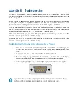
Страница 25: ...is open locate the COM ports described under Verifying Installation in the Installation and Configuration section of this manual Locate the COM ports for your device in Device Manager described under...

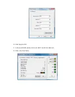
Страница 26: ...7 On the Port Information tab select the associated COM port and click the Open button 8 This will first open the COM port From this tab the port can also be closed See image below Click the Settings...

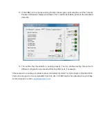
Страница 27: ...10 Click Apply and OK 11 In the main WinSSD window click on the BERT tab Bit Error Rate test 12 Click on the Start button...

Страница 28: ...rifies that the adapter is working properly You can continue testing this port with different configuration or proceed with testing other ports if necessary If these steps do not solve your problem pl...

Страница 29: ...Equipment and Data Circuit Terminating Equipment Employing Serial Binary Data Interchange Both implementations are in widespread use and will be referred to as RS 232 in this document RS 232 is capab...

Страница 30: ...ly 1 1 5 or 2 An extra bit used for error detection is often appended before the stop bits The diagram below demonstrates asynchronous communication bits This special bit is called the parity bit Pari...

Страница 31: ...Appendix E Cable Drawing...

Страница 32: ...b site Please refer to this to answer many common questions This section can be found at http www sealevel com faq asp Sealevel Systems maintains a web page on the Internet Our home page address is ww...

Страница 33: ...e obtained by delivering the Product to Sealevel and providing proof of purchase Customer agrees to ensure the Product or assume the risk of loss or damage in transit to prepay shipping charges to Sea...

Отзывы: