86
Module removal and replacement
3.
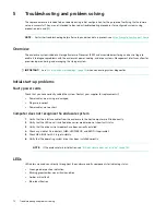
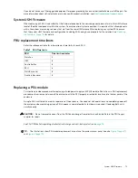
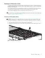
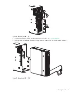
Revolve each swing-arm upward to release the PCBA carrier from its slot as shown in
Figure 69 Removing a HS Expander (2 of 2)
4.
While grasping the swing-arm handle, pull upwards to lift the HS Expander and remove it from its slot.
Installing an HS Expander module
Refer to
when performing this procedure, but ignore the directional arrow. You will insert the
module into the slot rather than remove it.
IMPORTANT:
Handle the HS Expander module carefully to avoid damage to the connector and swing arms.
1.
Check for damage, especially to all module connectors.
2.
Align the HS Expander module for use in the module slot that is accessible from the top panel along the right wall of
the enclosure.
3.
Insert the HS Expander module into the slot, and gently press down on the module until it seats firmly in its
connector.
4.
Verify that the HS Expander Status LED is off. Verify that the front panel LED states show no amber module faults.
5.
If replacing multiple HS Expanders, repeat
6.
Reattach top main bay cover
A
when you complete the procedure.
Replacing a drive carrier module
A DISC drive module consists of a DISC in a carrier. DISC Drive in Carrier (DDIC) modules are hot-swappable, which means
they can be replaced without halting I/O to the DISC groups, or powering off the enclosure. The new DISC must be of the
same type, and possess capacity equal to or greater than the one being replaced. Otherwise, the storage system cannot
use the new DISC to reconstruct the DISC group. Open the top main bay cover
A
respective half to access DDICs. See
, and
for enclosure cover locations. Reattach top respective main bay cover
A
half when the
procedure is completed. If accessing DDICs in DISC slots 96–105, remove top auxiliary bay cover
B
, and reattach it when
the procedure is completed. See also
for DISC slot indexing.

