64
Installation
3.
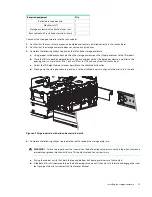
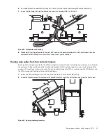
For the ease of installation, please note the data cable slots numbering as shown below.
Figure 54 Date cable slots indexing
4.
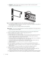
Connect data cables 1-5 into their respective IOM slots.
5.
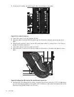
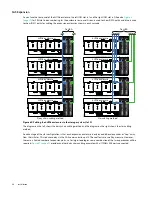
Route data cables 1–5 onto the CMA shelf and through the CMA brackets in the order and configuration shown
below.
6.
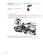
Rotate the cable capture arm which is near the IOM, close over data cables 1–5, ensuring it seats in the C-flange in
between the two cable capture arms.
7.
Connect data cables 6-10 into their respective IOM slots.
8.
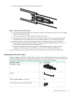
Route data cables 6–10 onto the CMA shelf and through the CMA brackets in the order and configuration shown
below.
Figure 55 Routing data cables from the IOMs and CMA cable capture arms
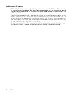
9.
Rotate the other CMA cable capture arm into the C bracket to secure the data cables 6 to 10. This CMA cable capture
arm may need to be pushed down in the C bracket. The CMA bracket may need to be shifted slightly in order for the
thumbscrew to find the PEM thread in the CMA shelf.

