background image

52

Savvio 15K.2 SAS Product Manual, Rev. C

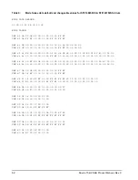
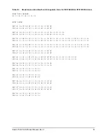
Table 9: 

Mode Sense data default and changeable values for ST9146852SS & ST9146752SS drives

MODE DATA HEADER:


00 00 05 12 8B 00 30 02

MODE PAGES:

DEF 81 0A C0 0B FF 00 00 00 05 00 FF FF


CHG 81 0A FF FF 00 00 00 00 FF 00 FF FF


DEF 82 0E 00 00 00 00 00 00 00 00 01 3A 00 00 00 00

CHG 82 0E 00 00 00 00 00 00 00 00 FF FF 00 00 00 00


DEF 83 16 BB D0 00 00 00 00 03 80 04 C4 02 00 00 01 00 E0 00 4C 40 00 00 00

CHG 83 16 00 00 00 00 00 00 FF FF 00 00 00 00 00 00 00 00 00 00 00 00 00 00

DEF 84 16 00 EC BD 04 00 00 00 00 00 00 00 00 00 00 00 00 00 00 3A A7 00 00

CHG 84 16 00 00 00 00 00 00 00 00 00 00 00 00 00 00 00 00 00 00 00 00 00 00

DEF 87 0A 00 0B FF 00 00 00 00 00 FF FF

CHG 87 0A 0F FF 00 00 00 00 00 00 FF FF

DEF 88 12 14 00 FF FF 00 00 FF FF FF FF 80 20 00 00 00 00 00 00

CHG 88 12 A5 00 00 00 FF FF FF FF 00 00 20 00 00 00 00 00 00 00

DEF 8A 0A 02 00 00 00 00 00 00 00 05 57

CHG 8A 0A 03 F0 00 00 00 00 00 00 00 00

DEF 18 06 06 00 00 00 00 00

CHG 18 06 00 00 00 00 00 00

DEF 99 06 06 00 07 D0 00 00

CHG 99 06 10 00 FF FF FF FF

DEF 9A 0A 00 02 00 00 00 0A 00 00 8C A0

CHG 9A 0A 00 03 FF FF FF FF FF FF FF FF

DEF 9C 0A 10 00 00 00 00 00 00 00 00 01

CHG 9C 0A 9D 0F FF FF FF FF FF FF FF FF

DEF 80 06 00 80 0F 00 00 00


CHG 80 06 B7 C0 8F 00 00 00

Содержание 15K.2 - Savvio 146.8 GB Hard Drive

Страница 1: ...Product Manual Savvio 15K 2 SAS 100516230 Rev C July 2009 Standard Models ST9146852SS ST973452SS Self Encrypting Drive Models ST9146752SS ST973352SS ...

Страница 2: ...l other trademarks or regis tered trademarks are the property of their respective owners When referring to hard drive capacity one gigabyte or GB equals one billion bytes Your computer s operating system may use a different standard of measurement and report a lower capacity In addition some of the listed capacity is used for formatting and other func tions and thus will not be available for data ...

Страница 3: ...characteristics 10 4 3 Start stop time 10 4 4 Prefetch multi segmented cache control 11 4 5 Cache operation 11 4 5 1 Caching write data 12 4 5 2 Prefetch operation 12 5 0 Reliability specifications 13 5 1 Error rates 13 5 1 1 Recoverable Errors 13 5 1 2 Unrecoverable Errors 13 5 1 3 Seek errors 14 5 1 4 Interface errors 14 5 2 Reliability and service 14 5 2 1 Annualized Failure Rate AFR and Mean T...

Страница 4: ...covery procedures 37 8 3 SAS system errors 38 8 4 Background Media Scan 39 8 5 Media Pre Scan 39 8 6 Deferred Auto Reallocation 39 8 7 Idle Read After Write 40 9 0 Installation 41 9 1 Drive orientation 41 9 2 Cooling 42 9 3 Drive mounting 43 9 4 Grounding 43 10 0 Interface requirements 44 10 1 SAS features 44 10 1 1 Task management functions 44 10 1 2 Task management responses 44 10 2 Dual port su...

Страница 5: ...Savvio 15K 2 SAS Product Manual Rev C iii 10 7 Additional information 61 11 0 Seagate Technology support services 62 ...

Страница 6: ...iv Savvio 15K 2 SAS Product Manual Rev C ...

Страница 7: ...second 26 Figure 5 73GB models 6 0 Gbit DC current and power vs input output operations per second 27 Figure 6 73GB models 3 0 Gbit DC current and power vs input output operations per second 27 Figure 7 Location of the HDA temperature check point 28 Figure 8 Recommended mounting 30 Figure 9 Dimensions 33 Figure 10 Physical interface 41 Figure 11 Air flow 42 Figure 12 Physical interface 55 Figure 1...

Страница 8: ......

Страница 9: ...s were called Full Disk Encryption FDE models before a differentiation between drive based encryption and other forms of encryp tion was necessary Product data communicated in this manual is specific only to the model numbers listed in this manual The data listed in this manual may not be predictive of future generation specifications or requirements If you are designing a system which will use on...

Страница 10: ...duct manual 2 1 1 Electromagnetic compatibility The drive as delivered is designed for system integration and installation into a suitable enclosure prior to use The drive is supplied as a subassembly and is not subject to Subpart B of Part 15 of the FCC Rules and Regulations nor the Radio Interference Regulations of the Canadian Department of Communications The design characteristics of the drive...

Страница 11: ...ustralian C Tick If this model has the C Tick Marking it complies with the Australia New Zealand Standard AS NZ CISPR22 and meets the Electromagnetic Compatibility EMC Framework requirements of Australia s Spectrum Manage ment Agency SMA Korean MIC If these drives have the Korean Communications Commission KCC logo they comply with paragraph 1 of Article 11 of the Electromagnetic Compatibility cont...

Страница 12: ...oducts These systems include standard operat ing procedures that ensure that restricted substances are not utilized in our manufacturing operations labora tory analytical validation testing and an internal auditing process to ensure that all standard operating procedures are complied with 2 2 Reference documents SCSI Commands Reference Manual Seagate part number 100293068 SAS Interface Manual Seag...

Страница 13: ...ve provisions for Security of Data at Rest based on the standards defined by the Trusted Computing Group see www trustedcomputing group org The head and disc assembly HDA is sealed at the factory Air recirculates within the HDA through a non replaceable filter to maintain a contamination free HDA environment Note Never disassemble the HDA and do not attempt to service items in the sealed enclosure...

Страница 14: ... correction length of 520 bits No preventive maintenance or adjustments required Dedicated head landing zone Embedded servo design Automatic shipping lock Self diagnostics performed when power is applied to the drive Zone bit recording ZBR Vertical horizontal or top down mounting Dynamic spindle brake 16 Mbyte data buffer see Section 4 5 Drive Self Test DST Background Media Scan BMS Idle Read Afte...

Страница 15: ...e same time provide users with flexibility if they choose Seagate recommends product planning in one of two modes Seagate designs capacity points at certain block sizes that Seagate guarantees current and future products will meet We recommend customers use this capacity in their project planning as it ensures a stable operating point with backward and forward compatibility from generation to gene...

Страница 16: ...ing on sparing scheme and sector size requested Single unit shipping pack The drive is normally shipped in bulk packaging to provide maximum protection against transit damage Units shipped individually require additional protection as provided by the single unit shipping pack Users planning single unit distribution should specify this option The Safety and Regulatory Agency Specifications part num...

Страница 17: ...m Avg rotational latency 2 0 2 0 msec 4 2 Seek performance characteristics See Section 10 4 1 SAS physical interface on page 55 and the SAS Interface Manual part number 100293071 for additional timing details 4 2 1 Access time Including controller overhead 2 1 1 Execution time measured from receipt of the Command to the Response msec Average Typical 4 3 3 Typical access times are measured under no...

Страница 18: ...time The drive accepts the commands listed in the SAS Interface Manual less than 3 seconds after DC power has been applied If the drive receives a NOTIFY ENABLE SPINUP primitive through either port and has not received a START STOP UNIT command with the START bit equal to 0 the drive becomes ready for normal operations within 20 seconds excluding the error recovery procedure If the drive receives ...

Страница 19: ...for the moment That is the drive does not check in the buffer segments for the requested read data but goes directly to the medium to retrieve it The retrieved data merely passes through some buffer segment on the way to the host All data transfers to the host are in accordance with buffer full ratio rules See the explanation provided with the information about Mode Page 02h disconnect reconnect c...

Страница 20: ...ommand after the data has been transferred into the cache but before the data has been written to the medium If an error occurs while writing the data to the medium and Good status has already been returned a deferred error will be gen erated The Synchronize Cache command may be used to force the drive to write all cached write data to the medium Upon completion of a Synchronize Cache command all ...

Страница 21: ... is determined using read bits transferred for recoverable errors occurring during a read and using write bits transferred for recoverable errors occurring during a write 5 1 2 Unrecoverable Errors An unrecoverable data error is defined as a failure of the drive to recover data from the media These errors occur due to head media or write problems Unrecoverable data errors are only detected during ...

Страница 22: ... the specifications in Section 6 4 may increase the product AFR decrease the MTBF The AFR MTBF is a population statistic not relevant to individual units The AFR MTBF specification is based on the following assumptions for Business Critical Storage System environments 8 760 power on hours per year 250 average on off cycles per year Operations at nominal voltages Systems will provide adequate cooli...

Страница 23: ...at the next scheduled interrupt is in two hours You can interrogate the drive through the host to determine the time remaining before the next scheduled mea surement and data logging process occurs To accomplish this issue a Log Sense command to log page 0x3E This allows you to control when S M A R T interruptions occur Forcing S M A R T with the RTZ command resets the timer Performance impact S M...

Страница 24: ...ive 2 Signals the host if the temperature exceeds a user specified value 3 Saves a S M A R T data frame on the drive which exceeds the threatening temperature value A temperature sensor monitors the drive temperature and issues a warning over the interface when the tem perature exceeds a set threshold The temperature is measured at power up and then at ten minute intervals after power up The therm...

Страница 25: ...f the number of retries required to recover the data The following conditions are considered DST failure conditions Seek error after retries are exhausted Track follow error after retries are exhausted Read error after retries are exhausted Write error after retries are exhausted Recovered errors will not be reported as diagnostic failures 5 2 6 2 Implementation This section provides all of the in...

Страница 26: ...t the beginning of the self test results log parameter section of the log page Existing data will be moved to make room for the new parameter block The drive reports 20 param eter blocks in the log page If there are more than 20 parameter blocks the least recent parameter block will be deleted The new parameter block will be initialized as follows 1 The Function Code field is set to the same value...

Страница 27: ... a particular drive can be determined by calling Seagate Customer Service at 1 800 468 3472 You can also determine remaining warranty using the Seagate web site www seagate com The drive serial number is required to determine remaining warranty information Shipping When transporting or shipping a drive use only a Seagate approved container Keep your original box Sea gate approved containers are ea...

Страница 28: ...equirements for a single drive are shown below Values indicated apply at the drive connector The standard drive models and the SED drive models have identical hardware however the security and encryption portion of the drive controller ASIC is enabled and functional in the SED models This represents a small additional drain on the 5V supply of about 30mA and a commensurate increase of about 150mW ...

Страница 29: ...7 0 06 Peak operating current random read Typical DC 1 6 0 45 0 41 0 46 0 41 Maximum DC 3σ 1 0 47 0 41 0 48 0 41 Maximum peak DC 3σ 1 14 1 24 1 16 1 22 Peak operating current random write Typical DC 1 0 51 0 32 0 53 0 32 Maximum DC 3σ 1 0 54 0 33 0 55 0 32 Maximum peak DC 3σ 1 16 1 22 1 16 1 20 Peak operating current sequential read Typical DC 1 0 88 0 22 0 90 0 22 Maximum DC 3σ 1 0 90 0 22 0 92 0...

Страница 30: ... the drive heads are relocated every 60 seconds to a random location within the band from three quarters to maximum track Table 3 ST973452SS ST973352SS DC power requirements Notes 3 0 Gbit mode 6 0 Gbit mode Amps Amps Amps Amps Voltage 5V 12V 2 5V 12V 2 Regulation 5 5 5 2 5 5 2 Avg idle current DC 1 7 0 36 0 18 0 37 0 18 Maximum starting current peak DC DC 3σ 3 0 51 1 09 0 51 1 08 peak AC AC 3σ 3 ...

Страница 31: ...ng current must be available to each device 4 Parameters other than spindle start are measured after a 10 minute warm up 5 No terminator power 6 2 1 Conducted noise immunity Noise is specified as a periodic and random distribution of frequencies covering a band from DC to 10 MHz Maximum allowed noise values given below are peak to peak measurements and apply at the drive power connector 6 2 2 Powe...

Страница 32: ...24 Savvio 15K 2 SAS Product Manual Rev C 6 2 3 Current profiles The 12V and 5V current profiles for the Savvio 15K 2 SAS drives are shown below Figure 1 Current profile for 146GB models ...

Страница 33: ...Savvio 15K 2 SAS Product Manual Rev C 25 Figure 2 Current profile for 73GB models Note All times and currents are typical See Tables 2 and 3 for maximum current requirements ...

Страница 34: ...te BTUs per hour multiply watts by 3 4123 Figure 3 146GB models 6 0 Gbit DC current and power vs input output operations per second 146GB models in 3 0 Gbit operation Typical power dissipation under idle conditions in 3 0 Gbit operation is 4 32 watts 14 74 BTUs per hour To obtain operating power for typical random read operations refer to the following I O rate curve see Figure 3 Locate the typica...

Страница 35: ...r hour multiply watts by 3 4123 Figure 5 73GB models 6 0 Gbit DC current and power vs input output operations per second 73GB models in 3 0 Gbit operation Typical power dissipation under idle conditions in 3 0 Gbit operation is 3 96 watts 13 51 BTUs per hour To obtain operating power for typical random read operations refer to the following I O rate curve see Figure 3 Locate the typical I O rate f...

Страница 36: ...out impact to specified MTBF Air flow may be needed to achieve these tempera tures Continual or sustained operation at case temperatures above these values may degrade MTBF The maximum allowable continuous or sustained HDA case temperature for the rated MTBF is 122 F 50 C To confirm that the required cooling for the electronics and HDA is provided place the drive in its final mechanical configurat...

Страница 37: ... Shock may be applied in the X Y or Z axis b Operating abnormal Equipment as installed for normal operation does not incur physical damage while subjected to intermit tent shock not exceeding 40 Gs at a maximum duration of 11 msec half sinewave and 25 Gs as a maxi mum duration of 2 msec half sinewave Shock occurring at abnormal levels may promote degraded operational performance during the abnorma...

Страница 38: ...ze Packaged product weight Drop height 600 cu in 9 800 cu cm Any 60 in 1524 mm 600 1800 cu in 9 800 19 700 cu cm 0 20 lb 0 to 9 1 kg 48 in 1219 mm 1800 cu in 19 700 cu cm 0 20 lb 0 to 9 1 kg 42 in 1067 mm 600 cu in 9 800 cu cm 20 40 lb 9 1 to 18 1 kg 36 in 914 mm Drives packaged in single or multipacks with a gross weight of 20 pounds 8 95 kg or less by Seagate for general freight shipment shall w...

Страница 39: ...ak 350 500 Hz swept sine 1 0 G zero to peak 10 500 Hz random 0 0118 G2 Hz Vibration may be applied in the X Y or Z axis 6 4 5 Air cleanliness The drive is designed to operate in a typical office environment with minimal environmental control 6 4 6 Corrosive environment Seagate electronic drive components pass accelerated corrosion testing equivalent to 10 years exposure to light industrial environ...

Страница 40: ...operating mode shall be 3 35 bels typical when measured to ISO 7779 specification There will not be any discrete tones more than 10 dB above the masking noise on typical drives when mea sured according to Seagate specification 30553 001 There will not be any tones more than 24 dB above the masking noise on any drive 6 4 8 Electromagnetic susceptibility See Section 2 1 1 1 ...

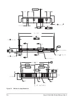
Страница 41: ... to Figure 9 for detailed mounting configuration dimensions See Section 9 3 Drive mounting Figure 9 Dimensions Height 0 5708 in 14 50 mm Width 2 7598 in 70 10 mm Depth 3 9547 in 100 45 mm Weight ST9146852SS ST9146752SS 0 444 lbs ST973452SS ST973352SS 0 429 lbs 0 201 kg 0 195 kg ...

Страница 42: ...BC mode to encrypt all data prior to being written on the media and to decrypt all data as it is read from the media The encryption engines are always in operation cannot be disabled and do not detract in any way from the performance of the drive The 32 byte Data Encryption Key DEK is a random number which is generated by the drive never leaves the drive and is inaccessible to the host system The ...

Страница 43: ...rCycle to ensure that the data bands will be locked if power is lost This scenario occurs if the drive is removed from its cabinet The drive will not honor any data read or write requests until the bands have been unlocked This prevents the user data from being accessed without the appropriate credentials when the drive has been removed from its cabinet and installed in another system When the dri...

Страница 44: ...efore the drive will allow the download operation 1 The download must be an SED file A standard base drive non SED file will be rejected 2 The download file must be signed and authenticated 3 As with a non SED drive the download file must pass the acceptance criteria for the drive For example it must be applicable to the correct drive model and have compatible revision and customer status 7 8 Powe...

Страница 45: ...list is not altered after factory formatting Locations of defects found and reallocated during error recovery procedures after drive shipment are listed in the G list defects growth list The P and G lists may be referenced by the initiator using the Read Defect Data command Details of the SCSI commands supported by the drive are described in the SAS Interface Manual Also more information on the dr...

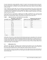
Страница 46: ...egradation of the unrecovered error rate For example suppose the read write recovery page has the RC bit set to 0 read retry count set to 4 and the recovery time limit set to 450 A four LBA Read command is allowed to take up to 295 26 msec recov ery time for each block and a maximum of 450 msec recovery for all four blocks If either of these limits is reached and a block has not yet been recovered...

Страница 47: ...been found by the host system during critical data accesses early in the drive s life The default setting for Media Pre Scan is enabled on standard products Media Pre Scan checks each write command to determine if the destination LBAs have been scanned by BMS If the LBAs have been verified the drive proceeds with the normal write command If the LBAs have not been verified by BMS Pre Scan will conv...

Страница 48: ...em requests the drive reads recently written data from the media and compares it to valid write command data resident in the drives data buffer Any sectors that fail the comparison result in the invocation of a rewrite and auto reallocation process The process attempts to rewrite the data to the original location If a verification of this rewrite fails the sector is re mapped to a spare location ...

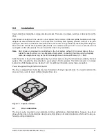
Страница 49: ...he drive in a non backplane host system connecting the drive using high quality cables is acceptable as long as the I O cable length does not exceed 4 meters 13 1 feet Slide the carrier or tray into the appropriate bay in your host system using the instructions provided by the host system This connects the drive directly to your system s SAS connector The SAS connector is normally located on a SAS...

Страница 50: ...he least amount of air flow resistance is created while providing air flow to the electronics and HDA Also the shortest possible path between the air inlet and exit should be chosen to minimize the travel length of air heated by the drive and other heat sources within the rack cabinet or drawer environment If forced air is determined to be necessary possible air flow patterns are shown in Figure 1...

Страница 51: ...our mounting points fixed and evaluating the out of plane deflection of the fourth mounting point when a known force F is applied to the fourth point 9 4 Grounding Signal ground PCBA and HDA ground are connected together in the drive and cannot be separated by the user The equipment in which the drive is mounted is connected directly to the HDA and PCBA with no electri cally isolating shock mounts...

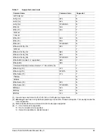
Страница 52: ...nt functions Table 5 lists the SAS task management functions supported 10 1 2 Task management responses Table 6 lists the SAS response codes returned for task management functions supported Table 5 SAS task management functions supported Task name Supported Abort Task Yes Clear ACA Yes Clear task set Yes Abort task set Yes Logical Unit Reset Yes Query Task Yes Table 6 Task management response code...

Страница 53: ...rt clocking e g both ports can run at 6Gbit sec or the first port can run at 6Gbit sec while the second port runs at 3Gbit sec The supported link rates are 1 5 3 0 or 6 0 Gbits sec Subject to buffer availability the Savvio drives support Concurrent port transfers The drive supports receiving COMMAND TASK management transfers on both ports at the same time Full duplex The drive supports sending XFE...

Страница 54: ...MED bit supported Y VS vendor specific N Inquiry 12h Y Date Code page C1h Y Device Behavior page C3h Y Firmware Numbers page C0h Y Implemented Operating Def page 81h Y Jumper Settings page C2h Y Supported Vital Product Data page 00h Y Unit Serial Number page 80h Y Lock unlock cache 36h N Log Select 4Ch Y PCR bit Y DU bit N DS bit Y TSD bit Y ETC bit N TMC bit N LP bit N Protocol specific Log Page ...

Страница 55: ...h Y 2 Caching Parameters page 08h Y Control Mode page 0Ah Y Disconnect Reconnect 02h Y Error Recovery page 01h Y Format page 03h Y Information Exceptions Control page 1Ch Y Backgound Scan mode subpage 01h Y Notch and Partition Page 0Ch N Protocol Specific Port page 19h Y Power Condition page 1Ah Y Rigid Disc Drive Geometry page 04h Y Unit Attention page 00h Y Verify Error Recovery page 07h Y Xor C...

Страница 56: ...ense 03h Y Actual Retry Count bytes Y Extended Sense Y Field Pointer bytes Y Reserve 16h Y 3rd Party Reserve Y Extent Reservation N Reserve 10 56h Y 3rd Party Reserve Y Extent Reservation N Rezero Unit 01h Y Search Data Equal 31h N Search Data High 30h N Search Data Low 32h N Seek 6 0Bh Y Seek 10 2Bh Y Send Diagnostics 1Dh Y Supported Diagnostics pages 00h Y Translate page 40h Y Set Limits 33h N S...

Страница 57: ...Verify 12 AFh N Verify 16 AFh N Verify 32 7Fh 000Ah N Write 6 0Ah Y Write 10 2Ah Y DPO bit Y FUA bit Y Write 12 AAh N Write 16 8Ah N Write 32 7Fh 000Bh N Write and Verify 10 2Eh Y DPO bit Y Write and Verify 12 AEh N Write and Verify 16 8Eh N Write and Verify 32 7Fh 000Ch N Write Buffer modes 0 2 supported 3Bh Y Write Buffer 3Bh Firmware Download option modes 5 7 Ah and Bh 3 Y Write Long 10 3Fh Y W...

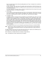
Страница 58: ...odel of drive The table above shows the hex values for Model ST9146852SS Refer to the values below for the values of bytes 16 through 26 of your particular model ST9146752SS 53 54 39 31 34 36 37 35 32 53 53 ST973452SS 53 54 39 37 33 34 35 32 53 53 ST973352SS 53 54 39 37 33 33 35 32 53 53 10 3 2 Mode Sense data The Mode Sense command provides a way for the drive to report its operating parameters t...

Страница 59: ...e value can be changed A zero 0 indicates the value is not changeable For example in Table 9 refer to Mode page 81 in the row entitled CHG These are hex numbers representing the changeable values for Mode page 81 Note in columns 5 and 6 bytes 04 and 05 there is 00h which indicates that in bytes 04 and 05 none of the bits are changeable Note also that bytes 06 07 09 10 and 11 are not changeable bec...

Страница 60: ... 00 00 00 00 00 00 00 00 00 00 00 00 00 3A A7 00 00 CHG 84 16 00 00 00 00 00 00 00 00 00 00 00 00 00 00 00 00 00 00 00 00 00 00 DEF 87 0A 00 0B FF 00 00 00 00 00 FF FF CHG 87 0A 0F FF 00 00 00 00 00 00 FF FF DEF 88 12 14 00 FF FF 00 00 FF FF FF FF 80 20 00 00 00 00 00 00 CHG 88 12 A5 00 00 00 FF FF FF FF 00 00 20 00 00 00 00 00 00 00 DEF 8A 0A 02 00 00 00 00 00 00 00 05 57 CHG 8A 0A 03 F0 00 00 00...

Страница 61: ... 00 00 00 00 00 00 00 00 00 00 00 00 00 3A A7 00 00 CHG 84 16 00 00 00 00 00 00 00 00 00 00 00 00 00 00 00 00 00 00 00 00 00 00 DEF 87 0A 00 0B FF 00 00 00 00 00 FF FF CHG 87 0A 0F FF 00 00 00 00 00 00 FF FF DEF 88 12 14 00 FF FF 00 00 FF FF FF FF 80 20 00 00 00 00 00 00 CHG 88 12 A5 00 00 00 FF FF FF FF 00 00 20 00 00 00 00 00 00 00 DEF 8A 0A 02 00 00 00 00 00 00 00 02 D1 CHG 8A 0A 03 F0 00 00 00...

Страница 62: ...on N Synchronized locked spindle operation Y Segmented caching N Zero latency read Y Queue tagging up to 128 queue tags supported Y Deferred error handling Y Parameter rounding controlled by Round bit in Mode Select page 0 Y Reporting actual retry count in Extended Sense bytes 15 16 and 17 N Adaptive caching Y SMP 1 in Mode Select command needed to save RPL and rotational offset bytes Table 12 Mis...

Страница 63: ... the SAS device connector J1 Figures 13 and 14 provide the dimensions of the SAS connector Details of the physical electrical and logical characteristics are provided within this section The operational aspects of Seagate s SAS drives are provided in the SAS Interface Manual Figure 12 Physical interface ...

Страница 64: ... 1 27 6X 1 27 14X 15 875 0 35MIN 15 875 33 43 0 05 B 4 90 0 08 0 84 0 05 22X 0 15 B P15 P1 S7 S1 SEE Detail1 0 30 0 05 4X 4 00 0 08 0 15 D 0 30 0 05 2X 41 13 0 15 B B C C A A 0 20 B 42 73 REF C OF DATUM D L 1 10 R0 30 0 08 4X 2 00 3X 5 08 0 45 0 03 7X 0 10 M E 4 65 0 80 6X 7 62 5 92 0 52 0 08 x 45 ...

Страница 65: ... x 45 5X 0 40 0 05 X 45 3X CORING ALLOWED IN THIS AREA 2 25 0 05 4 85 0 05 0 10 B E S14 S8 4 40 0 15 SEE Detail 2 3 90 0 15 SECTION A A SECTION C C A 0 35 0 05 45 R0 30 0 08 C 1 95 0 08 0 08 0 05 1 23 0 05 0 08 0 05 Detail 2 CONTACT SURFACE FLUSH TO DATUM A 0 03 65 30 1 90 0 08 SECTION B B 2 40 0 08 0 10 A D ...

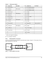
Страница 66: ...ure revision of this publication when production parts are available from major connec tor manufacturers The SAS device connector is illustrated in Figures 13 and 14 10 4 4 Electrical description SAS drives use the device connector for DC power SAS interface Activity LED This connector is designed to either plug directly into a backpanel or accept cables 10 4 5 Pin descriptions This section provid...

Страница 67: ...Volts S9 Port B_in Diff input pair P9 5 Volts S10 Port B_in P10 Ground S11 Port A Ground P11 Ready LED Open collector out S12 Port B_out Diff output pair P12 Ground S13 Port B_out P13 12 Volts charge S14 Port B Ground P14 12 Volts P15 12 Volts Short pin to support hot plugging NC No connection in the drive 10 4 6 SAS transmitters and receivers A typical SAS differential copper transmitter and rece...

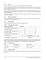
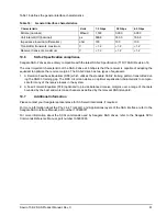
Страница 68: ...ame information 10 5 1 Ready LED Out The Ready LED Out signal is driven by the drive as indicated in Table 14 The Ready LED Out signal is designed to pull down the cathode of an LED The anode is attached to the proper 3 3 volt supply through an appropriate current limiting resistor The LED and the current limiting resis tor are external to the drive See Table 15 for the output characteristics of t...

Страница 69: ...rward Equalizer FFE optimized to provide balanced receive margins over a range of channels bounded by the best and worst case channels as defined by the relevant ANSI standard 10 7 Additional information Please contact your Seagate representative for SAS electrical details if required For more information about the Phy Link Transport and Applications layers of the SAS interface refer to the Seagat...

Страница 70: ...single password protected Web interface anytime anywhere in the world spp seagate com spp seagate com supports Seagate resellers with product information program benefits and sales tools You may register for customized communications that are not available on the web These communications contain product launch EOL pricing promotions and other channel related information To learn more about the ben...

Страница 71: ...nters are available on a global basis for the return of defective products See www sea gate com for the service center near you USA Canada Latin America support services For an extensive list of telephone numbers to technical support presales and warranty service in USA Canada Latin America including business hours go to the Contact Us page on www seagate com Global Customer Support Presales Techn...

Страница 72: ...64 Savvio 15K 2 SAS Product Manual Rev C ...

Страница 73: ...er data 6 space 11 busy status 54 C cache operation 11 cache segments 11 caching write data 12 Canadian Department of Communications 2 capacity unformatted 9 case temperature 28 CBC 34 CE Marking 3 check condition status 54 Cipher Block Chaining 34 class B limit 2 clear ACA function 44 clear task set function 44 commands supported 46 condensation 28 condition met good status 54 connector illustrat...

Страница 74: ...ution time 10 function complete code 00 44 not supported code 05 44 reject code 04 44 G Global Data Band 35 Good status 54 gradient 28 ground shift noise 59 grounding 43 H HDA 42 43 head and disc assembly HDA 5 head and disc assembly See HDA heads read write data 9 heat removal 42 heat source 42 host equipment 43 hot plugging the drive 14 humidity 28 humidity limits 28 I Idle Read After Write 40 i...

Страница 75: ...on operating vibration 31 O office environment 31 operating 28 29 31 option selection 58 orientation 29 out of plane distortion 43 P package size 30 package test specification 4 packaged 30 parameter rounding 54 password 34 35 passwords 35 PCBA 43 peak bits per inch 9 peak operating current 21 22 peak to peak measurements 23 performance characteristics detailed 9 general 10 performance degradation...

Страница 76: ...le unit shipping pack kit 8 SMART 7 15 SMP 1 in Mode Select command 54 SNW 3 training gap 61 Specification 61 spindle brake 6 standards 2 start stop time 10 support services 62 surface stiffness allowable for non flat surface 43 switches 41 synchronized spindle operation 54 system chassis 43 T task management functions 44 Abort task set 44 Clear ACA 44 Clear task set 44 terminate task 44 task mana...

Страница 77: ......
Страница 78: ...Seagate Technology LLC 920 Disc Drive Scotts Valley California 95066 4544 USA Publication Number 100516230 Rev C Printed in USA ...

Отзывы: