background image

«

APPENDIX A: COMMANDS LIST »  | 

51


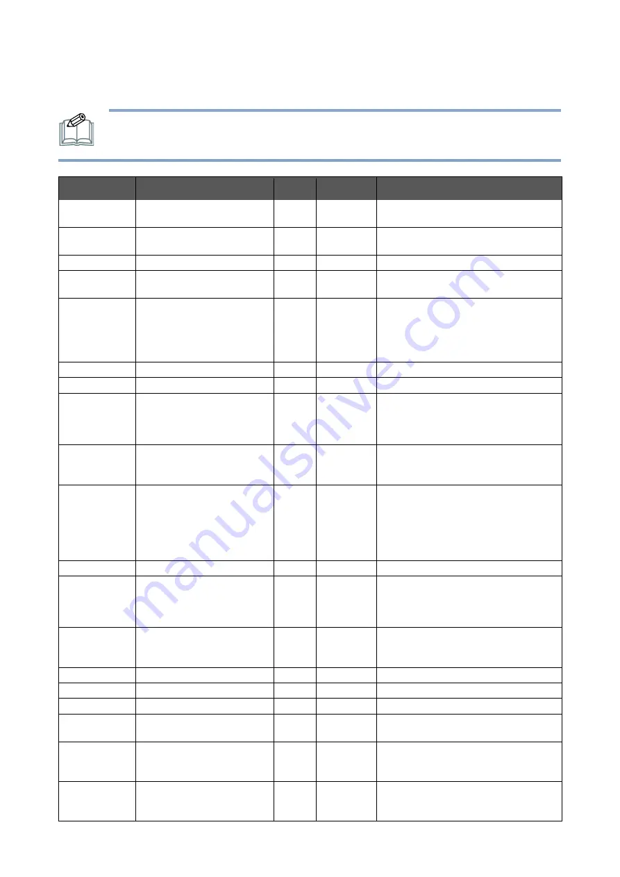
APPENDIX A: COMMANDS LIST 


NOTE: Refer to the “Communication Protocol” document for how to send commands 

to the display. 


Addr. 

Name 

R/W 

Default 

Description 

00h 

Monitor ID 

R/W 

0: set ID to 0, and accept a new ID. 1–99: 

set ID to x (only ID=0 can be set to x).   

01h 

Power Status 

R/W 

0: power off 

1: power on 

02h 

Volume 

R/W 

50 

0-100: audio volume 

03h 

Mute 

R/W 

0: mute off 

1: mute on 

04h 

Video Source 

R/W 

5: HDMI1 
6: HDMI2 

12: DisplayPort 

16: Slot 
17: USB (read only) 

05h 

Contrast Ratio 

R/W 

50 

0-100: contrast ratio 

06h 

Brightness 

R/W 

50 

0-100: brightness 

07h 

Color Temperature 

R/W 

0: 6500K 

1: 9300K 
2: 11500K 

3: User 

08h 

Anti-Burn-in 

R/W 

0: off 

1: on 
2: once 

09h 

Power Saving 

R/W 

0: Off 

1: 30s 

2: 60s 
3: 120s 

4: 240s 

5: 300s 

0Ah 

Backlight 

R/W 

72 

0-100: backlight 

0Dh 

Picture Mode 

R/W 

0: vivid 
1: standard 

2: soft 

3: user 

0Eh 

Color Range 

R/W 

0: auto 
1: 0–255 

2: 16–235 

1Ch 

User R Gain 

R/W 

50 

0–100. User red gain 

1Dh 

User G Gain 

R/W 

50 

0–100. User green gain 

1Eh 

User B Gain 

R/W 

50 

0–100. User blue gain 

25h 

Show Monitor ID 

W only 

0: hide the “Monitor ID” window 
1: show the “Monitor ID” window 

2Ah 

Aspect Ratio 

R/W 

0: auto 

1: 4:3 

2: full screen 

50h 

Detect Signal & Slot Power 

R/W 

0: Off 
1: On 

2: Slot Auto On-Off 

Содержание P550QVF07.0

Страница 1: ...USER MANUAL PUSDM55A P550QVF07 0 PUSDM65A P650QVF09 0 PUSDM75A SN75UNM01 0 V1 10 ...

Страница 2: ...y 13 Setting Down the Display 13 MOUNTING THE DISPLAY 14 Adjusting Directions 14 Wall Mount Specifications 15 FlatWall Installation 18 Protection from Overheating 19 SETTING UP THE DISPLAY 20 Main Components 20 Control Buttons 24 Connecting the Power Cable 26 CONNECTING THE DISPLAY 27 Using the DisplayPort 27 Using the HDMI Port 28 Using the USB Port 29 Using the RS232 Port 29 Connecting External ...

Страница 3: ...ng Media in the USB Flash Drive 46 TROUBLESHOOTING 50 APPENDIX A COMMANDS LIST 51 APPENDIX B HDMI CEC 53 OneTouch Play 53 System Standby 53 Remote Control Pass Through 53 APPENDIX C SPECIFICATIONS 54 APPENDIX D SUPPORTED TIMING 57 APPENDIX E SAFETY INFORMATION 58 Consignes de sécurité 58 Avertissements 59 APPENDICE F MONTAGE DE L AFFICHAGE 61 Réglage des directions 61 Spécifications de montage mur...

Страница 4: ...display Do not install the display in a confined environment If you want to mount the display in a recessed TV wall mount make sure to leave enough space around the display to ensure good ventilation and to avoid operation at an abnormal temperature Avoid excessive pressure or temperature changes as special liquid crystal material in the display may result in cracks scratches or damage When the di...

Страница 5: ...ord is unplugged from wall socket To fully disengage the power to the unit please disconnect the power cord from the ac outlet Do not remove cover or back No user serviceable parts inside Refer servicing to qualified service personnel CAUTION Please use the power cord provided with this monitor in accordance with the table below If a power cord is not supplied with this equipment please contact yo...

Страница 6: ...s no signal from the current input source When Detect Signal Slot Power is set to On or RS232 Switch is set to COM Port the display backlight will turn off after 60 seconds if it has no signal from the current input source NOTE When the Power Saving setting is set to On the display will meet the ENERGY STAR energy efficiency requirements When the Detect Signal Slot Power and RS232 Switch settings ...

Страница 7: ...and may produce eye fatigue due to insufficient contrast Suitable for entertainment purposes at controlled luminous environments to avoid disturbing reflections from the screen Cleaning the LCD Panel When the liquid crystal panel is dusty please gently wipe with a soft cloth Do not rub the LCD panel with hard material Do not apply pressure to the LCD surface Do not use oleic acid cleaner as it wil...

Страница 8: ...use harmful interference to radio communications Operation of this equipment in a residential area is likely to cause harmful interference in which case the user will be required to correct the interference at his own expense CE Declaration of Conformity Hereby AUO Inc declares that this LCD monitor is in compliance with the essential requirements and other relevant provisions of EMC Directive 201...

Страница 9: ... display The illustrations in this manual may differ from the actual product and items Display Remote Control and AAA Batteries Power Cord USA Taiwan Power Cord Europe Korea RS232 Cable IR Extender Quick Start Guide and Assorted Documents NOTE The IR extender features an LED that indicates the power status of the display Green The display is powered on Red The display is in stand by mode ...

Страница 10: ...isplay prepare a flat and stable surface near a wall outlet Set the product box in an upright position according to the arrow markings on the outside of the product box 1 Open the product box from the top of the box 2 Remove the accessories from the top of the EPE foam packaging cushion ...

Страница 11: ... MOVING THE DISPLAY 11 3 Pinch the four clip locks to the unlock position and pull to remove 4 Remove the upper case from the top of the box ...

Страница 12: ...12 MOVING THE DISPLAY 5 Remove the EPE foam packaging cushions 6 Pull down the HDPE bag around the display 7 Remove the display from the bottom case ...

Страница 13: ...g the Display When placing the display always keep the display upright or keep the screen face down as illustrated in the Setting Down the Display section Never tilt the display towards the left right or balanced on a single corner of the frame Setting Down the Display When setting the display down place the screen face down on a flat and stable surface covered by a protective sheet and a table cu...

Страница 14: ...unt may be purchased separately for easier installation If you want to use the display vertically or horizontally adjust the display such that the main power switch on the back of the display is pointing downward or rightward and the respective arrow on the rear of the display is pointed upward as illustrated below If the display is not mounted in such a way the display may not function properly H...

Страница 15: ...e or recessed area leave adequate room between the display and the enclosure in order to allow heat to disperse as shown below Make sure to provide air conditioning around the display or adequate ventilation so that heat can properly dissipate away from the unit and mounting accessories Please note the following DO NOT install in locations where a door can knock against the display DO NOT install ...

Страница 16: ... VESA mount 400 x 600mm for 65 Firmly secure a wall mount onto the display Use four M6 screws on the 55 displays maximum length 20mm maximum torque 18 kgf cm four M8 screws on the 65 displays maximum length 20mm maximum torque 20 kgf cm and four M6 screws on the 75 displays maximum length 10mm maximum torque 18 kgf cm NOTE Refer to the proper installation instructions included with the mounting eq...

Страница 17: ... MOUNTING THE DISPLAY 17 55 65 75 ...

Страница 18: ...ounting location for signs of damage or weakness that may occur over time Flat Wall Installation Installation on a Flat Wall Minimum Distance 40mm When installing the display on a wall face there has to be at least 40mm of space between the display and the wall for ventilation purposes The display must be installed in an environment with proper ventilation to prevent it from overheating Do not blo...

Страница 19: ...he BLU brightness will decrease to a level of about 10 Under these circumstances the user must check and ensure that there is enough space around the display for heat dissipation NOTE The threshold to trigger an ambient temperature warning code varies slightly depending on the way the display is set up For example for a display with multiple ports in use the threshold is 43 C while for a display w...

Страница 20: ...e details see Installing an SDM Module on page 31 5 SDM S Slot used to install a small Intel Smart Display Module SDM Small For more details see Installing an SDM Module on page 31 6 USB Connects with a flash drive to display digital media or update the display s firmware NOTE Use a flash drive with a maximum storage capacity of 512 GB for FAT32 NTFS formats 7 DP IN Connects with devices transmitt...

Страница 21: ...dule Connects with the IR OUT connector of another display to daisy chain the IR signal NOTE From the tip to the terminal the plug sections are defined as IR VCC LED Ground 13 RS232 IN Connects with the serial IO connector of a host device NOTE From the tip to the terminal the plug sections are defined as TX RX Ground 14 IR OUT Connects with the IR IN connector of another display to daisy chain th...

Страница 22: ... firmware NOTE Use a flash drive with a maximum storage capacity of 512 GB for FAT32 NTFS formats 5 DP IN Connects with devices transmitting audio video using the DP DisplayPort interface 6 HDMI IN1 Connects with devices transmitting audio video using the HDMI interface 7 HDMI IN2 Connects with devices transmitting audio video using the HDMI interface 8 HDMI OUT Connects with the HDMI IN connector...

Страница 23: ...the serial IO connector of a host device NOTE From the tip to the terminal the plug sections are defined as TX RX Ground 12 IR OUT Connects with the IR IN connector of another display to daisy chain the IR signal with a pin to pin straight cable featuring three conductor sections 13 RS232 OUT Connects with the RS232 IN connector of another display to daisy chain direct commands NOTE The RS232 OUT ...

Страница 24: ...d return to the previous menu 2 SOURCE Switches the video input source HDMI1 HDMI2 Slot DP Accept the changes made in the OSD menu 3 Plus Increases the volume of the display Moves the selection right or increase the values in the OSD menu 4 Minus Decreases the volume of the display Moves the selection left or decrease the values in the OSD menu 5 Up Moves the selection in the OSD menu up Plays med...

Страница 25: ...us Decreases the volume of the display Moves the selection left or decrease the values in the OSD menu 5 Plus Increases the volume of the display Moves the selection right or increase the values in the OSD menu 6 SOURCE Switches the video input source HDMI1 HDMI2 Slot DP Accept the changes made in the OSD menu 7 MENU Displays the On Screen Display OSD menu For more details see ON SCREEN DISPLAY OS...

Страница 26: ...rd repeatedly in a short period of time NOTE The supplied power cord varies depending on the country where you purchased this apparatus For all cases use a power cord that matches the AC voltage of the power outlet and has been approved by and complies with the safety standard of your country 3 Turn on the power switch CAUTION When disconnecting the AC power cord be sure to first disconnect the pl...

Страница 27: ...e to the DisplayPort output port on a computer or A V device 2 Connect the DisplayPort cable to the DisplayPort input port on the display 3 Press the SOURCE button of the remote control to select the video input source DP 4 Once selected the audio input setting will automatically switch to the correct audio source for the video connection NOTE Use DisplayPort cables with a maximum length of 3m ...

Страница 28: ...ter or A V device 2 Connect the HDMI cable to the HDMI 1 or HDMI 2 input port on the display 3 Press the SOURCE button of the remote control to select the video input source HDMI 1 HDMI 2 4 Once selected the audio input setting will automatically switch to the correct audio source for the video connection ...

Страница 29: ...ton to access the multimedia files in the USB flash drive See Playing Media in the USB Flash Drive on page 46 for more information Using the RS232 Port 1 Connect a RS232 cable to the RS232 output port on a computer 2 Connect the RS232 cable to the RS232 input port on the display 3 Enter commands on the computer based on the commands list included in the COMMANDS LIST section on page 51 ...

Страница 30: ...To connect external speakers to the display use an audio cable to connect the AUDIO OUT jack of the display to the speakers or sound systems NOTE The internal speakers will be muted when the display detects an audio cable is plugged into the AUDIO OUT jack ...

Страница 31: ...ce with HDMI 1 4 2 0 compatibility To install an Intel SDM module into the SDM slot on your display 1 Turn off the power switch on the display 2 For SDM S Modules Remove the 2 screws securing the metal SDM S slot cover on the right side of the display and remove the cover For SDM L Modules Remove the 4 screws securing the metal SDM L and SDM S slot covers on the right side of the display and remov...

Страница 32: ...M L Modules Re install the 2 screws to secure the SDM L module in place 5 Turn on the power switch on the display 6 Power on the display and press the SOURCE button of the remote control to select the video input source Slot NOTE Disable the Restore On AC Power Loss function in the BIOS setup utility of the SDM module otherwise the SDM module cannot be powered on normally ...

Страница 33: ...ipment turn off the main power switch before making connections To interconnect the displays in a daisy chain 1 Connect the video source to the HDMI IN2 port of the first display in the daisy chain 2 Use an HDMI cable to connect the HDMI output port of the first display to the HDMI IN2 port of the second display and so on for all subsequent displays 3 Set the video source of every display to HDMI2...

Страница 34: ...et up you can set a specific display to IR free status to overside the IR daisy chain and control only that display in the IR loop 1 Power on the specific display to be operated 2 Press the MENU button to display the OSD menu and select Setting Monitor ID to set a unique ID for each display 3 Press the F4 button on the remote control followed by the display s two digit monitor ID e g 01 and ENTER ...

Страница 35: ...ng connections To interconnect multiple displays for direct commands via the RS232 ports 1 Connect a computer to the RS232 input port of the first display 2 Use a 3 5mm cable to connect the RS232 output port of the first display to the RS232 input port on the second display and so on for all subsequent displays NOTE Use a 3 5mm cable with a 3 pin plug 3 Press the MENU button to display the OSD men...

Страница 36: ... 1 the display connected to display 1will be designated display 2 and so on To enable the Auto ID function you must first execute the following commands in the order shown below Command Description 00 06 00 00 00 00 88 1B Prepares all displays within the RS232 daisy chain to receive their ID at this point all display s IDs are still set to 0 00 06 00 00 00 01 49 DB Gives the first connected displa...

Страница 37: ...rol buttons Item Description 1 POWER Switches the power on off NOTE It takes about 10 seconds to power on the display 2 MENU Displays the OSD menu In the sub menu confirms the item selected in the OSD menu and return to the previous menu 3 Plays the previous media file 4 Up Down Left Right Moves the selection in the OSD menu 5 SLIDE SHOW Displays input source information 6 EXIT Exits the current m...

Страница 38: ...ideo input source Use the or buttons to directly select HDMI1 HDMI2 Slot DP 14 Hot Keys F1 Creates a playlist for the media files that have been selected NOTE Only files of the same type photo music movie and in the same drive can be grouped together under the same playlist F2 Deletes the existing playlists F3 Imports playlists F4 Sets a specific display to IR free status See the USING THE IR IN O...

Страница 39: ...y compartment LOCKING UNLOCKING THE REMOTE CONTROL The IR sensor for the display can be locked so that the remote control function is disabled To lock the IR sensor remote control 1 Press the MENU button on the remote control followed by 0 0 and 2 2 Once the remote control is locked a lock icon will appear on the top left corner of the display indicating that the remote control has been locked NOT...

Страница 40: ...o enter the sub menu 3 In the sub menu press the or button to choose the settings and then press or button to adjust the settings If there is a sub list under the sub menu press the ENTER button again to enter the sub list 4 Press the MENU button to confirm the settings and return to the previous menu OSD Menu Overview The following sections list the initial OSD functions in the main menu screen F...

Страница 41: ...o the signal source detected Color Temperature Adjusts the color temperature of the display 9300K 6500K User 11500K NOTE When the Color Temperature is set to User the display will present the native color gamut of the input source Aspect Ratio Adjusts the aspect ratio of the display Auto 4 3 Full Screen Backlight Adjusts the backlight brightness of the display 0 to 100 Color Range Changes the RGB ...

Страница 42: ...e and time for the display format DD Month YYYY HH MM NOTE The date and time will be reset when the power switch is turned off Off Time Allows the display to automatically power off at a pre configured time Off Once User The power off schedule can be set to execute on day s of the week in User mode On Time Allows the display to automatically power on at a pre configured time input source and volum...

Страница 43: ... input sources according to a pre configured sequence Select Enable and set up priority 1 to 5 to enable the function NOTE When setting up the USB port as the input source a unique media type photo music or movie must be designated The display does not support the Signal Priority function when SDM module in sleep mode HDMI CEC Enables Disables the HDMI CEC function Off On and configures the device...

Страница 44: ...omatically shut down the SDM module when the display is powered off When set to On only the display backlight will be turned off when the display is powered off When set to Slot Auto On Off the SDM module will be automatically turned on off when the display is powered on off NOTE To prevent the SDM module from being damaged it is suggested that you follow the standard power off procedure to shut d...

Страница 45: ... the display when a flash drive containing the firmware file is connected to the display s USB port Yes No Reset Resets the OSD menu to its default settings No Yes Information Lists the firmware version internal temperature and resolution of the display USB Plays media in the USB flash drive Item Description Multimedia Accesses the media files located on the flash drive connected to the USB port o...

Страница 46: ...es in a flash drive using the remote control 1 Insert the flash drive to the USB port on the display 2 Press the MENU button on the remote control to display the OSD menu 3 Use the button to select and then press the ENTER button to enter the sub menu 4 Use the button to select the media type Photo Music Movie you wish to play and then press the ENTER button to confirm the selection ...

Страница 47: ...sub menu Use the F1 button to create playlists F2 button to delete playlists and F3 button to import playlists 6 Use the buttons to navigate to the media file you want to play and press the ENTER button to confirm your selection 7 When a media file is being played Press the ENTER button to display the control buttons Use the buttons to navigate the control buttons Press the ENTER button to confirm...

Страница 48: ...nt A and B as end points to repeat the designated part of the music video file Plays all files randomly Plays background music for the photo slideshow Mutes the audio from the display Shows all files in the playlist Shows the file information Rotates the photo clockwise by 90 Rotates the photo counterclockwise by 90 Forwards the video slowly Jumps forward one frame Jumps to a designated time on th...

Страница 49: ...V MPEG1 1080P 30fps MPEG2 1080P 30fps MPEG4 1080P 30fps avi AVI MPEG2 1080P 30fps V V MPEG4 1080P 30fps H 264 1080P 30fps avi AVI Motion JPG 640X480 30fps V V Music File Extension Audio Codec Bit Rate Sample Rate mp3 MPEG1 Layer2 32Kbps 448Kbps 32Khz 48KHz mp3 MPEG1 Layer3 32Kbps 320Kbps 32Khz 48KHz N A work with video files only LPCM 64Kbps 1 5Mbps 8Khz 48KHz Photo File Extension Codec Format Pho...

Страница 50: ...t for the voltage to stabilize and then turn on off the display again with the remote control or AC switch If the display shows abnormal unstable unfocused distorted etc images 1 Check if the signal source device is properly connected to the display 2 In case of voltage instability wait for the voltage to stabilize and then turn on off the display again with the remote control or AC switch If the ...

Страница 51: ... 50 0 100 contrast ratio 06h Brightness R W 50 0 100 brightness 07h Color Temperature R W 1 0 6500K 1 9300K 2 11500K 3 User 08h Anti Burn in R W 0 0 off 1 on 2 once 09h Power Saving R W 2 0 Off 1 30s 2 60s 3 120s 4 240s 5 300s 0Ah Backlight R W 72 0 100 backlight 0Dh Picture Mode R W 1 0 vivid 1 standard 2 soft 3 user 0Eh Color Range R W 0 0 auto 1 0 255 2 16 235 1Ch User R Gain R W 50 0 100 User ...

Страница 52: ...riority 1 R W 0 0 Null default 1 HDMI 1 2 HDMI 2 3 Slot 4 DP 5 USB Photo 6 USB Music 7 USB Movie 67h Priority 2 R W 0 68h Priority 3 R W 0 69h Priority 4 R W 0 6Ah Priority 5 R W 0 6Bh Priority Enable R W 0 0 Disable 1 Enable 6Ch Priority Reset W N A 1 Reset all priority to be Null 0Fh Temperature Value R only 30 100 2Bh Reset W only 0 no action 1 system reset 2Dh IR Keypad Lock R W 0 0 Unlock IR ...

Страница 53: ...emote control One Touch Play The display will be automatically powered on when the input source is turned on with its remote control System Standby The display will automatically enter standby mode when the input source enters standby mode Remote Control Pass Through You can use the display s remote control to control the input source The supported keys are listed in the following table Operation ...

Страница 54: ... AC 100 240V 50 60Hz 2 7A Power Consumption typ max 139W 153W w o SDM 180W 198W w o SDM 200W 220W w o SDM Standby Power Watt AC 100V 0 5W 0 5W 0 5W Display Signal Input DP 1 2 x1 HDMI 2 0 x2 USB 2 0 x1 DP 1 2 x1 HDMI 2 0 x2 USB 2 0 x1 DP 1 2 x1 HDMI 2 0 x2 USB 2 0 x1 Signal Output HDMI 2 0 x1 Audio x 1 Signal output x1 via SDM optional HDMI 2 0 x1 Audio x 1 Signal output x1 via SDM optional HDMI 2...

Страница 55: ...C 0 C 40 C Storage Temp 20 C 60 C 20 C 60 C 20 C 60 C Operating Humidity 10 90 RH 10 90 RH 10 90 RH Storage Humidity 10 90 RH 10 90 RH 10 90 RH Display Orientation Landscape Portrait Landscape Portrait Landscape Portrait Usage 24 7 hrs days 24 7 hrs days 24 7 hrs days Accessory Power Cable US UL BSMI PSE 1 8M x1 EU CE KC 1 8M x1 US UL BSMI PSE 1 8M x1 EU CE KC 1 8M x1 US UL BSMI PSE 1 8M x1 EU CE ...

Страница 56: ... layers 1420 x 1844 x 1150 mm 286 5kg PUSDM65A P650QVF09 0 Box with display 1pcs box 1640 x 986 x 226 mm 30 9kg Pallet with boxes 5 boxes pallet 1 layer 1660 x 1116 x 1150 mm 172 5kg Pallet 18kg Pallet 1660 x 130 x 1150 mm 10 boxes pallet 2 layers 1660 x 2102 x 1150 mm 327kg PUSDM65A P650QVF09 0 Box with display 1pcs box 1800 x 1070 x 280 mm 55 5kg Pallet with boxes 4 boxes pallet 1 layer 1820 x 1...

Страница 57: ...ng UHD 3840x2160 30Hz 3840x2160 30Hz Video Timing FHD 480p 60Hz 720x480 4 3 480p 60Hz 720x480 4 3 480i 60Hz 720x480 4 3 576p 50Hz 720 x 576 16 9 576p 50Hz 720x576 16 9 720p 60Hz 1280x720 576i 50Hz 720x576 4 3 720p 50Hz 1280x720 720p 60Hz 1280x720 1080i 50Hz 1920x1080 720p 50Hz 1280x720 1080p 30Hz 1920x1080 1080i 50Hz 1920x1080 1080p 25Hz 1920x1080 1080p 30Hz 1920x1080 1080p 24Hz 1920x1080 1080p 25...

Страница 58: ...ectez toujours tous les avertissements et toutes les étiquettes d instructions apposés sur l affichage N installez pas l affichage dans un environnement confiné Si vous souhaitez installer l affichage dans un support mural encastré pour téléviseur veillez à laisser suffisamment d espace autour de l affichage pour assurer une bonne ventilation et éviter un fonctionnement à une température anormale ...

Страница 59: ...N Pour réduire le risque de choc électrique assurez vous que le cordon d alimentation est débranché de la prise murale Pour débrancher complètement l appareil débranchez le cordon d alimentation de la prise secteur N enlevez pas le couvercle ou le dos Ne contient aucune pièce réparable par l utilisateur Confiez toute réparation à un personnel qualifié ATTENTION Veuillez utiliser le cordon d alimen...

Страница 60: ...使用者會被要求採取某些適當的對策 視力警語 使用過度恐傷害視力 使用 30 分鐘請休息 10 分鐘 未滿 2 歲兒童不看螢幕 2 歲以上每 天看螢幕不要超過 1 小時 安全注意事項 警告 為了減少火災或觸電風險 請勿將本裝置暴露在雨中或濕氣中 注意 有觸電危險 請勿開啟 注意 為了避免觸電 請勿拆卸機殼 內部並沒有可供使用者維修的零件 若等邊三角形內含有一個箭頭的閃電符 號 其目的是用於警告使用者 本產品內 部含有未絕緣的 危險電壓 可能對人 體構成觸電危險 若等邊三角形中含有驚嘆號的符號 其目 的是用於提醒使用者 本裝置隨附的手冊 中含有重要的操作及保養維修指示 ...

Страница 61: ...roximité REMARQUE Il est possible d acheter séparément un support mural pour faciliter l installation Si vous voulez utiliser l affichage verticalement ou horizontalement réglez l affichage de manière à ce que l interrupteur principal situé à l arrière de l affichage soit dirigé vers le bas ou vers la gauche comme illustré ci dessous Si l affichage n est pas monté de cette manière il risque de ne ...

Страница 62: ...ffisant entre l affichage et l enceinte afin de permettre à la chaleur de se disperser comme indiqué ci dessous Veillez à prévoir une climatisation ou une ventilation adéquate autour de l affichage afin que la chaleur puisse être correctement dissipée de l appareil et des accessoires de montage Veuillez noter ce qui suit NE PAS installer l affichage dans des endroits où il risquerait d être cogné ...

Страница 63: ...A sur l affichage à l aide de quatre vis M6 longueur maximale 20 mm couple maximum 18 kgf cm Pour 65 fixez fermement un support VESA sur l affichage à l aide de quatre vis M8 longueur maximale 20 mm couple maximum 20 kgf cm Pour 75 fixez fermement un support VESA sur l affichage à l aide de quatre vis M6 longueur maximale 10 mm couple maximum 18 kgf cm REMARQUE Reportez vous aux instructions d ins...

Страница 64: ...64 APPENDICE F MONTAGE DE L AFFICHAGE 55 65 75 ...

Страница 65: ...el qualifié pour le faire réparer Vérifiez régulièrement l emplacement de montage pour déceler tout signe de dommage ou de faiblesse qui pourrait survenir au fil du temps Installation sur mur plat Installation sur un mur plat Distance minimale 40 mm Lors de l installation de l affichage sur un mur un espace d au moins 40 mm doit être ménagé entre l affichage et le mur à des fins de ventilation L a...

Отзывы: