


4
IN
AU
STRAL
IA
PR
OU
DLY BUILT
Continued Over.../
INSTRUCTIONS -
ELECTRICINEMA TYPE A, B & C
Connect IP Projection Screen
THE PROJECTION SCREEN CAN BE OPERATED IN FIVE WAYS:
1. INFRA-RED REMOTE CONTROL
•
The projection screen is packaged with a 2 channel Infra
Red Transmitter and a 300mm long IR Sensor, already
connected to the screen and exiting the rear of the
canister.
•
Position the IR Sensor Eye with double sided tape or
a U Pin, so that it can be seen from where you wish to
operate the projection screen, and use the up and down
buttons on the transmitter on channels 1 or 2 to operate
the screen.
2. DRY CONTACT CLOSURE
•
This is the industry standard method of switching a
projection screen via a Building Control System, such as
AMX, Crestron, C-Bus, etc…etc
•
It is operated on a momentary contact switching
standard with an Open, Close and Common input port.
It utilises the same connection as the above described
Impulse Wall Switch.
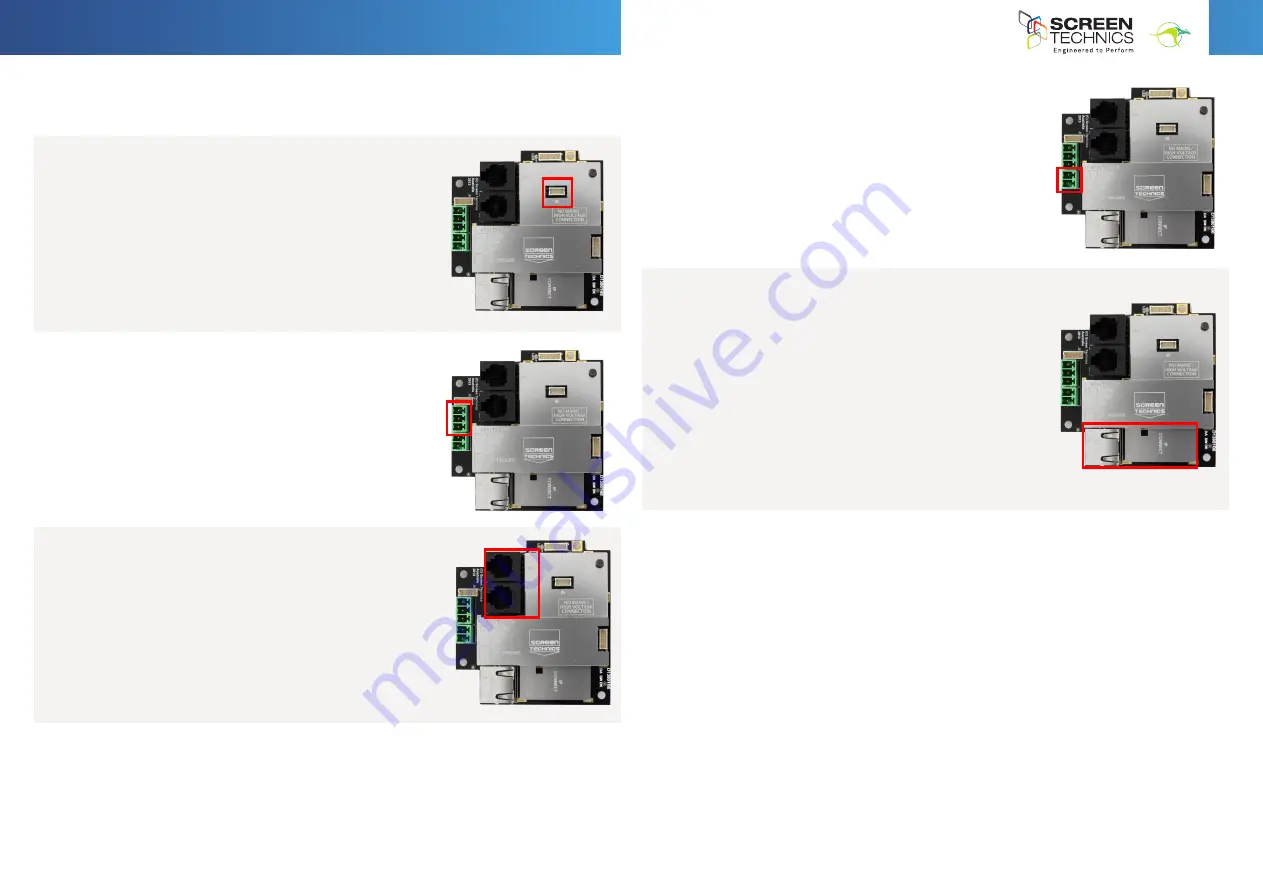
3. DAISY CHAIN LINK TO OTHER CONNECT MODULES (CABLE
SUPPLIED BY OTHERS)
•
RJ12 6 Core Straight Through Data cable can link up to 8
Connect controlled devices for multiple switching.
4. LOW VOLTAGE TRIGGER
•
Switches device upon the receipt of 3v to 24v DC from
a projectors low volt output port, plugs into the phoenix
connector on the module.
•
Not polarity sensitive.
5. IP CONTROL RJ45
•
Due to the detailed nature of the user instructions
associated with this method of control we direct you
to the associated document – Electricinema IP Control
Instructions V1.0
•
However for a beginners guide to basic control functions
please download from
screentechnics.com.au
the PC
Connect or Mac Connect software and this will assist
you in identifying the Connect Module and provide basic
control, then guide you by web browser to communicate
and program the individual Module.
•
Note: You will have to connect the screen module to a
network to be able to utilise this software.
Note: As the Infra-Red control is also used to perform a Connect module reset in case you are
troubleshooting any performance issues, it is recommended that the IR cable be left attached
to the module even if it is not the chosen operating method for your installation.
Screen Technics Connect Control Module
– Comes standard on all Electricinema Products
Please note the control input ports for this device is located in the RIGHT HAND SIDE of the screen canister and is
totally
LOW VOLTAGE.
The LEFT HAND SIDE contains the HIGH VOLTAGE motor controller only and is not to be
accessed for general use.
After the physical installation of the Electricinema is completed, plug the screen into a standard power point and turn on. The
screen comes with a standard 3 pin power plug which suitable for Australian and New Zealand GPO’s (general power outlet).
The projection screen can be operated in five ways:
Infra-Red Remote Control
The projection screen is packaged with a 2 channel Infra Red Transmitter and a 300mm long IR Sensor, already
connected to the screen and exiting the rear of the canister.
Position the IR Sensor Eye with double sided tape or a U Pin, so that it can be seen from where you wish to
operate the projection screen, and use the up and down buttons on the transmitter on channels 1 or 2 to
operate the screen.
Dry Contact Closure
This is the industry standard method of switching a projection screen via a Building Control System, such as
AMX, Crestron, C-Bus, etc…etc
It is operated on a momentary contact switching standard with an Open, Close and Common input port. It
utilises the same connection as the above described Impulse Wall Switch.
Daisy Chain Link to other Connect Modules (cable supplied by others)
RJ12 6 Core Straight Through Data cable can link up to 8 Connect controlled devices for multiple switching.
Low Voltage Trigger
Switches device upon the receipt of 3v to 24v DC from a projectors low volt output port, plugs into the phoenix
connector on the module.
Not polarity sensitive.
IP Control RJ45
Due to the detailed nature of the user instructions associated with this method of control we direct you to the
associated document – Electricinema IP Control Instructions V1.0
However for a beginners guide to basic control functions please download from
www.screentechnics.com.au
the PC Connect or Mac Connect software and this will assist you in identifying the Connect Module and provide
basic control, then guide you by web browser to communicate and program the individual Module.
Note: You will have to connect the screen module to a network to be able to utilise this software.
Note: As the Infra-Red control is also used to perform a Connect module reset in case you are troubleshooting any performance
issues, it is recommended that the IR cable be left attached to the module even if it is not the chosen operating method for your
installation.
Limit Setting for Connect ElectriCinema Screens
The following instructions are for the adjustment of the limit switches that alter the upper
and lower stop positions on "Connect" ElectriCinema Screens only
Where are The Limit Switches?
At the opposite end to the power cable (ie on the Right Hand Side).
One switch is accessible through the slat rod opening and the other is behind a rubber grommet
towards the front of the canister.
Which Switch is for Up and Down?
Down switch - Accessible through the rubber grommet
Up switch - Accessible through the slat rod opening
What Tools do I Need?
Either the limit setting tool (supplied), a narrow tip screw driver (less than 4mm) or a
4mm Allen Key
Which Way do I Turn the Switch?
Clockwise always increases the amount of rotation (travel) of the motor.
Anti-clockwise always reduces the amount of rotation (travel) of the motor.
So pick the switch responsible for the limit position, up or down. Clockwise turning of the switch will always let the motor travel
further in that direction. Anti-clockwise turning of the switch will lessen the amount of travel in that direction.
Can I adjust the switch while the screen is sitting on the limit - ie fully up or down?
Clockwise adjustment? – YES. But it is better to back the screen away from the limit and then adjust
Anti-clockwise adjustment? - NO you will damage the micro switch if you turn it anti-clockwise while the screen is sitting on the limit.
Never attempt this. You must back the screen away from the limit
before adjustment. After adjustment you will need to run the screen up and down to pick up the new limit
Will I void the product warranty if I damage the screen whilst making these adjustments?
Yes.


