Note: If the perimeter sensor is armed for more than 10 days, the battery safeguard will
automatically disable the perimeter sensor.
Note: Although the system will work in any position or mounting angle, try to avoid placing the
MCM with the bell of the siren facing toward either side of the bike; this may reduce sensitivity
(Planning the Installation cont)
1.
Check that your motorcycle battery is fully charged and that all electrical circuits are
in good working condition.
2.
Check the layout and construction of the motorcycle to decide what space is
available to place the components.
3. Verify that no moving parts interfere with the components or their wires.
4. Do not route wires near sharp edges, which could cut wires and cause a short.
5. Do not mount components near extreme heat areas such as exhaust pipes
6. Allow at least an inch or two of slack at all connection points to reduce the chance
that a connection will break apart due to vibration.
7 Do not drill any holes; mount the components with the provided Velcro and cable ties.
Mounting the Components
Select a suitable location under the seat or in a side cover. Mount the MCM using Velcro
or cable ties. Make sure that it is not exposed or easily reached.
Routing the RFID Antenna
Make sure to place the RFID antenna as close as possible to where the remote will be
when you are turning your key on to disarm the alarm. The RFID range depending on
obstructions is 2-3 feet.
Routing the Antenna Wire
The MCM includes an 18” antenna wire. The first 12” is a coaxial wire; the remaining 6” is
the actual antenna wire. When routing, try to avoid running the antenna along or near
metal. For best performance, try to have at least a portion of the antenna wire exposed.
Wire Connections
The MCM is equipped with two connectors. One is for the main harness (HAR-1) and the
other is for the optional accessories.
Accessory Harness
Plug in the accessory harness to the matching connector on the MCM. Each one of the
connectors on the accessory harness is unique and can only be connected to the correct
accessory. If no options are being used plug in the supplied dust cover.
4
Main Harness
If the optional factory connector kit is being used, please disregard this section of the
instructions and refer to the instructions that were supplied with the factory connector kit
.
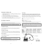
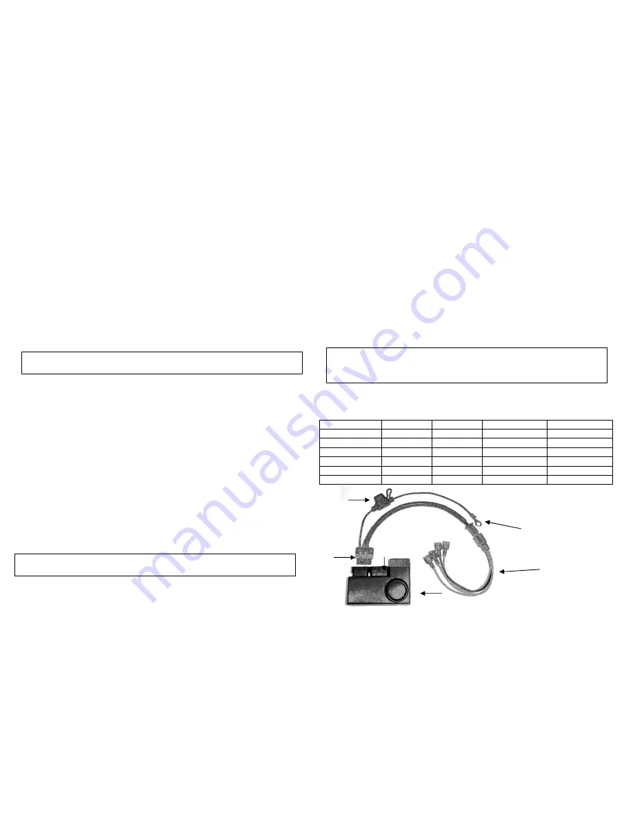
The main harness consists of two harnesses. One is labeled (HAR-1) and the second is
labeled (GEN-1). Plug in the white 4 pin connector from the (HAR-1) into the matching 4
pin connector from the (GEN-1). The (HAR-1) also has a waterproof connector that plugs
into the MCM. The wires should be connected as follows:
HAR-1
Black wire with fuse and ring terminal – To battery Positive (+).
GEN-1
Black wire – To ground (-).
Grey wire – To turn signal power wire (Left).
Grey wire – To turn signal power wire (Right).
Orange wire – To tail light wire OR any other wire that is hot (+) when ignition is ON (NOTE:
this is an input to the alarm this connection is not designed to flash the tail light).
Note: When the main harness (HAR-1) is plugged in, the siren should chirp and turn signals should
flash twice. If the siren does not chirp; check the fuse, battery power (+) and ground (-) connections.
If the turn signal lights do not flash make sure that the grey wires are connected to the turn signal
power (+) wires. Connecting these wires incorrectly may damage the system.
Color Codes:
Ground (-)
Tail Light
Left Turn Signal
Right Turn Signal
Honda
Green wire
Brown wire
Orange wire
Blue wire
Kawasaki
Black wire
Red wire
Green wire
Grey wire
Suzuki
Black/White Brown wire
Green or Black
Grey wire
Yamaha
Black wire
Blue wire
Green wire
Brown wire
Harley Davidson
Black wire
Blue wire
Brown wire
Purple wire
Ducati
Black wire
Yellow wire
White/Black
wire
White/Green
wire
Fuse
To Battery (+)
Accessory
HAR-1 Connector
GEN-1
Black – To Ground (-)
MCM Grey – To Turn Signal
Grey – To Turn Signal
Orange – To Tail Light
5


