

CONFIGURATION
If the transmitter is already configured as required by the application (sensor type,
range, etc), it may be installed and used right away. However, if a distinct
configuration is required, this can be done through the TxConfig software and the
TxConfig Interface.
The TxConfig interface and software can be purchased from the manufacturer or at its
authorized distributors and representatives. Updates for the software are available at
our website. To install the TxConfig software, run the Tx_setup.exe file and follow the
instructions.
Serial port configuration errors may occur when other devices are sharing the
same port (ex.: Palm Hot Sync). Close all serial port applications prior to using
the TxConfig software.
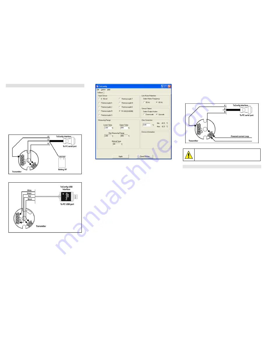
The TxConfig interface connects the transmitter to the PC, as shown in Figures 01
and 02. There are two types of interface: TxConfig-RS232 and TxConfig-USB.
Figure 01 – TxConfig Interface connections model RS232
Figure 02 – TxConfig Interface USB connections
Once the connection is accomplished, the software shows the configuration options
of the transmitter model attached. Access the Help for usage instructions.
The TxConfig screen in shown in Figure 3.
Figure 03 – TxConfig main screen
The fields in the screen mean:
1.
Input Sensor: Choose the desired temperature sensor among the available
options. See Table 01.
2.
Measuring Range: Defines the output scale for the input sensor. Program here
the measurement Lower Range Value and the Upper Range Value.
When the Lower Range Value is configured with a value higher than the Upper
Range Value, the current output will have a decrescent behavior (20~4 mA).
The values chosen for the limits must lay within the sensor span as shown in
this same field. Also, each sensor has a its own minimum span value, as
indicated in the screen
.
See Table 01.
3.
Line Noise Rejection: The transmitter incorporates a digital filter to cancel the
induced noise from the 50 or 60 Hz systems. For better performance, select the
line frequency used in your country.
4.
Sensor Failure Detection: establishes the transmitter output behavior (upscale or
down-scale) in the presence of a sensor fail.
5.
Zero Correction: Allows for small sensor corrections. See item Operation.
6.
Read Configuration: Brings to the screen the current transmitter parameters
configuration.
7.
Apply: Sends a new configuration to the transmitter.
8.
Device Information: The Device Information box contains relevant data
concerning a particular transmitter. Please pass along this information when
contacting the technical assistance department.
Note: The factory default configuration is (unless otherwise specified or ordered):
y
Pt100 input, 0 to 100 ºC;
y
60 Hz filtering and upscale (20 mA) output for sensor fail.
The transmitter must be powered in order to be configured. The TxConfig-USB
interface provides the needed power.
The TxConfig-RS232 interface, however, requires an auxiliary supply for guarantee
reliable communication with the computer. An external 9V battery can be used for this
purpose (Figure 01). An alternative is to configure the transmitter while it is in operation;
this way, the needed energy is supplied by the current loop, as in Figure 04.
Figure 04 – TxConfig Interface connections – Loop powered
The TxConfig interfaces contain dedicated circuitry for proper
communication between transmitters and computer. Always make use of
the TxConfig interfaces for configuration purposes, otherwise the
transmitters may get damaged, voiding the warranty.
OPERATION
All input types are factory calibrated. Recalibration in the field is not recommended,
but can be accomplished through the TxConfig software. Contact the factory for the
calibration procedures.
When necessary, fine adjustments to the transmitter output current can be
accomplished directly at the transmitter. For this, short circuit transmitter terminals 1
and 4. After 2 seconds, the output current starts to increase gradually until it
reaches 0.8 mA above the initial value. After reaching that value, it drops to 0.8 mA
below the initial value, increasing gradually again. The user must monitor the current
and open the circuit when the current reaches the desired value.
The offset correction can also be accomplished through the TxConfig software. The
TxConfig interface can be connected to the transmitter while it is operating in the
process (Figure 04). See in Figure 03 the Zero Correction field for this purpose.
The user must choose the sensor and configure the sensor span which best suit the
application. The sensor span must not exceed the maximum range supported by the
transmitter for a particular sensor, neither be lower than the minimum span.
It is important to note that the transmitter accuracy is related to the total sensor span
of a sensor, regardless of the output scale (span) configured. Example:
y
Pt100; maximum input span of –200 to +650 °C, 0.2% accuracy.
y
Maximum error: 1,7 °C ( 0,2 % of 850 °C )
y
This error is the same no matter if total span is used (-200 to 650 °C) or a
narrower user-defined span is used, like 0 to 100 °C.
Note: When using a Pt100 simulator, make sure the TxBlock’s Pt100 excitation
current (0.17 mA) is compatible with the simulator specification.


