3.0 Initial Setup
|9
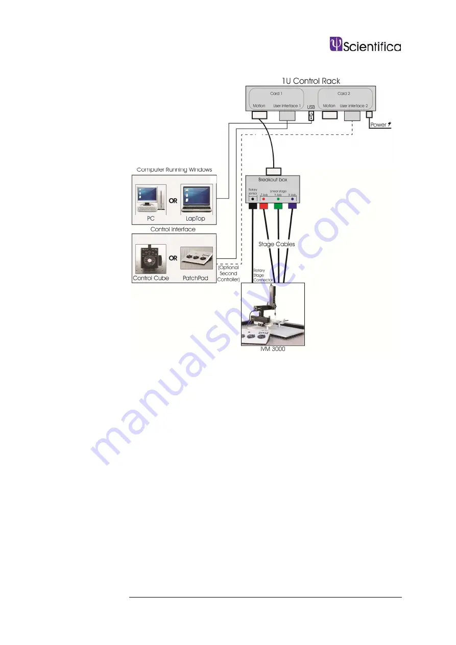
3.3.3. IVM electrical setup diagram
Страница 1: ...Triple Axes In Vivo Micromanipulator Setup and Operation Manual Revision 2 0 Manual Part No S IVM 3000 Manual...
Страница 2: ...Scientifica Ltd 1A Kingfisher Court Brambleside Bellbrook Industrial Estate Uckfield TN22 1QQ United Kingdom Tel 44 0 1825 749 933 Fax 44 0 1825 749 934 info scientifica uk com...
Страница 3: ...robe holder accessory 7 3 2 4 Axon Dovetail Adapter Plate 7 3 3 Electrical setup of the IVM 7 3 3 1 Control racks 7 3 3 2 Connecting the IVM to the control rack and user interface 8 3 3 3 IVM electric...
Страница 4: ...or Z Rotary Motion 15 8 3 8 Manipulators Follow Control 15 8 3 9 Manipulators Creeper 16 8 3 10 Manipulators PPL Wheel ReMap 16 8 3 11 View 16 8 3 12 View Show Stored Points 17 8 3 13 Approach 19 8 3...
Страница 5: ...fety information appears throughout the manual Adjustment or removal of any screws or components other than those noted in this manual can adversely affect the performance and operation of your microm...
Страница 6: ...Dovetail rod probe holding assembly PH 1000 4 Aluminium fastening strip 5 Stereotaxic frame 6 Z axis motorised body 7 Y axis motorised body 8 X axis motorised body 9 Stoelting bracket IVM 545 00 10 IV...
Страница 7: ...ches Y to X IVM 535 00 3 Axis IVM Kopf Mount IVM 575 00 IVM Angle Block Assembly Attaches X to Z IVM 525 00 Extended probe holder accessory IVM 530 00 Dove tail probe holder accessory PH 1000 IVM Stat...
Страница 8: ...micromanipulators IVM X Y and Z 1U controller rack PatchPad One user interface and connecting cable 25 Way to 25 Way Parallel Cable User interface cable 15 way D type to RJ45 Breakout box Mains power...
Страница 9: ...Building the IVM The IVM 3000 is comprised of three separate single axis manipulators connected by brackets shown in the figure below The IVM comes with a range of brackets for mounting alternative c...
Страница 10: ...x axis IVM blue micrometres into the dovetailed clamp and lock into position by tightening the screws on the aluminium fastening strip 3 2 2 Attaching the dove tail probe holder accessory Dove tail mo...
Страница 11: ...ter plate The dove tail adapter plate should be inserted into the dove tail clamp of the IVM and then secured by tightening the four screws on the aluminium fastening strip 3 3 Electrical setup of the...
Страница 12: ...ed on 1 Connect the IVM manipulator RJ45 connector red to the breakout box provided ensuring that the colour of the connector corresponds with the colour of the reference dot on the breakout box 2 Con...
Страница 13: ...3 0 Initial Setup 9 3 3 3 IVM electrical setup diagram...
Страница 14: ...plied Functionality of each user interface type is described as follows 4 2 1 Using a Control Cube Figure A Control Cube user interface Device selection Located on the side of the cube Selects which d...
Страница 15: ...on must be set first before Home In can be used To set Home Out move the IVM to the desired position then press H out for 3 seconds to store the current position Subsequent pressing of Home Out will c...
Страница 16: ...in Linlab to control a different axis if required Review the Linlab operation manual for more information Device selection switch I II Selects which device to control when two devices and one user int...
Страница 17: ...or 3 seconds to store the current position Subsequent pressing of Home Out will cause the IVM to move out to the stored Home Out position until an alternative Home Out position is stored The Home In p...
Страница 18: ...14 4 0 Operation Guide 5 0 Maintenance WARNING Do not tamper with any fixings other than those indicated in the manual for mounting purposes There are no user serviceable parts within the IVM 3000...
Страница 19: ...ay also be a source of drift Check that the headstage mounted sliding bracket is clamped at the end of its travel Is the pipette holder attached firmly and the O ring new and of appropriate size With...
Страница 20: ...lted down onto the table top Is the cooling headstage switched off Some amplifiers have a cooling facility on the headstage which is normally located on the amplifier front or back panel This may lead...
Страница 21: ...0 Specifications Number of axes 3 Travel 70 mm Step size 20 nm Speed minimum 0 1 m per second maximum 4 mm per second Mechanical Resolution 1 m Load Capacity 0 2 Kg Temperature range Operation 15 to...
Страница 22: ...4 7 0 Dimensional Drawings 7 0 Dimensional Drawings All dimensions are in mm Travel extension Front Top Bottom Side...
Страница 23: ...0 XP and Windows 7 1 Insert the supplied CD into your drive PC only 2 Run the LinLabsetup XX_XX XX exe file 3 Follow the instructions on the screen to complete the installation 8 1 1 Connecting the sy...
Страница 24: ...When running the system on Windows XP or Windows 2000 the operating system should detect a new USB device on power up or connection The following screen will appear Select No not this time Select to...
Страница 25: ...ected Note The LinKey driver installation is complete at this point please skip to the section Identifying USB port assignment on the next page Again select No not this time And install from list or a...
Страница 26: ...ed to the USB port To do this open Control Panel from the Start Menu select System Hardware Device Manger and then expand Ports COM LPT your USB serial Port will be displayed as below in this case as...
Страница 27: ...pose of the software is to give you complete control over the set up parameters of your motorised device The following features are in place to optimise the usage of the system 8 2 Running the softwar...
Страница 28: ...urrent position will remain as it was prior to switching off 8 2 2 Step Control This function enables the user to drive each axis by a specific amount The user can select any step size between 0 001 a...
Страница 29: ...e device to its original position prior to Homing Out less any safety offset which may have been applied using the Set Home In Offset function within the Manipulator menu described below For Manipulat...
Страница 30: ...rack and continue If running a single device the following screen allows you to set the correct comms port 8 3 2 Configure System Configuration This allows the user to automatically configure individu...
Страница 31: ...you want to do this Once selected the current position is stored as the Home Out position 8 3 4 Manipulator Set Home In Offset This allows you to apply an offset of between 10 mm and 10 mm in micron s...
Страница 32: ...r with a virtual axis the step will be applied to the combined axes If an approach angle has not been set the step will only apply to the Z axis 8 3 6 Manipulator Reverse X Y or Z Direction Units This...
Страница 33: ...erse the effect of the controller movement i e If you turn the control clockwise and the stage moves to the right click on the Reverse X Joystick and the stage will then move in the opposite direction...
Страница 34: ...is menu to set the speed and the distance to be moved 8 3 10 Manipulators PPL Wheel ReMap PPL Wheel re map allows you to swap round which wheels control the different axes To change click Next until t...
Страница 35: ...positions In order to store a point within LinLab drive the manipulator or microscope stage to the required location and select AddPoint from the stored points form This will cause the following scree...
Страница 36: ...p down menu If you want to cycle through the points select Start Auto Run This will go from one point to the next in a sequential fashion pausing for the time set in the Delay field default is 1000ms...
Страница 37: ...eleration for computerised Point to Point moves ie between Home In and Home Out or Memory positions Changes to the acceleration setting also apply to the deceleration value If the user experiences res...
Страница 38: ...K or Apply button is selected If the user wants to return to the default settings select default and Apply or OK 8 4 Programming linear motion and Heater Cards Scientifica are happy to provide a summa...
Страница 39: ...at the velocity specified for each axis ABS Move Absolute This moves to a new Absolute position for the three axis Tabs commas or spaces separate the arguments ABS X Y Z where X Y and Z are positions...
Страница 40: ...Set User Units Z As Above DATE Make Date and version This reports the Firmware Version compile date and compile time PROG Enter Program mode This puts the unit into programming mode ready for Firmwar...
Страница 41: ...Set Home in offset This sets the home in Offset for use by the IN command SET Set Home Out position This sets the position the manipulator will go to when OUT is sent to the current position SETSTEP S...
Страница 42: ...ill not apply if the instrument has been damaged by accident misuse or as a result of modification by persons other than Scientifica Ltd personnel Before returning an instrument please obtain a return...
Страница 43: ...nds placed on the equipment of electrophysiologists and thinking laterally around these challenges we ve developed an impressive product range used in laboratories throughout the world including many...
Страница 44: ...Scientifica Ltd 1A Kingfisher Court Brambleside Bellbrook Industrial Estate Uckfield TN22 1QQ United Kingdom Tel 44 0 1825 749 933 Fax 44 0 1825 749 934 info scientifica uk com...