


4.72
SEL-787 Relay
Instruction Manual
Date Code 20081022
Protection and Logic Functions
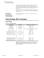
Logic Settings (SET L Command)
Logic Settings (SET L Command)
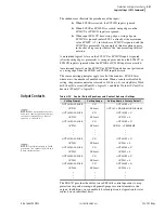
Settings associated with latches, timers, counters, math variables, and output
contacts are listed below. Note that SEL
OGIC
equations are processed every
quarter cycle while math variable equations and analog quantities are updated
every 100 ms and 500 ms, respectively.
SEL
OGIC
Enables
shows the enable settings for latch bits (ELAT), SEL
OGIC
control
equations (including timers) (ESV), Counters (ESC), and math variable
equations (EMV). This helps limit the number of settings that you need to
make. For example, if you need six timers, only enable six timers.
IMPORTANT:
Upon relay initial
power up or Port 1 setting changes or
Logic setting changes, the user may
have to wait up to two minutes before
an additional setting change can
occur. Note that the relay is functional
with protection enabled, as soon as
the
ENABLED LED
comes ON (about 5—10
seconds from power up).
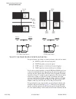
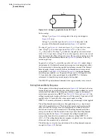
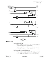
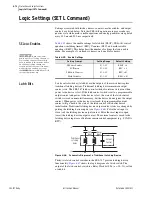
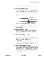
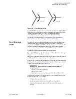
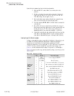
Latch Bits
Latch control switches (latch bits are the outputs of these switches) replace
traditional latching devices. Traditional latching devices maintain output
contact state. The SEL-787 latch control switch also retains state even when
power to the device is lost. If the latch control switch is set to a programmable
output contact and power to the device is lost, the state of the latch control
switch is stored in nonvolatile memory, but the device de-energizes the output
contact. When power to the device is restored, the programmable output
contact will go back to the state of the latch control switch after device
initialization. Traditional latching device output contact states are changed by
pulsing the latching device inputs (see
). Pulse the set input to
close (set) the latching device output contact. Pulse the reset input to open
(reset) the latching device output contact. The external contacts wired to the
latching device inputs are often from remote control equipment (e.g., SCADA,
RTU).
Figure 4.46
Schematic Diagram of a Traditional Latching Device
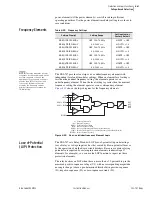
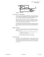
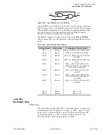
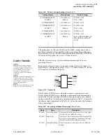
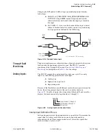
Thirty-two latch control switches in the SEL-787 provide latching device
functionality.
shows the logic diagram of a latch switch. The
output of the latch control switch is a Relay Word bit LT
n
(
n
= 01–32), called
a latch bit.
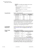
Table 4.25
Enable Settings
Setting Prompt
Setting Range
Default Setting
SEL
OGIC
Latches
N, 1–32
ELAT := 4
SV/Timers
N, 1–32
ESV := 5
SEL
OGIC
Counters
N, 1–32
ESC := N
Math Variables
N, 1–32
EMV := N
Set
Input
Reset
Input
Output
Contact
Traditional
Latching
Relay
(+)
(–)
Содержание SEL-787
Страница 1: ...20081022 SEL 787 Transformer Protection Relay Instruction Manual PM787 01 NB ...
Страница 6: ...This page intentionally left blank ...
Страница 12: ...This page intentionally left blank ...
Страница 18: ...This page intentionally left blank ...
Страница 78: ...This page intentionally left blank ...
Страница 206: ...This page intentionally left blank ...
Страница 280: ...This page intentionally left blank ...
Страница 334: ...This page intentionally left blank ...
Страница 376: ...This page intentionally left blank ...
Страница 388: ...This page intentionally left blank ...
Страница 474: ...This page intentionally left blank ...
Страница 508: ...This page intentionally left blank ...
Страница 522: ...This page intentionally left blank ...