SEL-787-2, -3, -4 Data Sheet
Schweitzer Engineering Laboratories, Inc.
34
Specifications
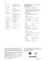
Compliance
Designed and manufactured under an ISO 9001 certified quality
management system
49 CFR 15B, Class A
This equipment has been tested and found to comply with the limits
for a Class A digital device, pursuant to part 15 of the FCC Rules.
These limits are designed to provide reasonable protection against
harmful interference when the equipment is operated in a
commercial environment. This equipment generates, uses, and can
radiate radio frequency energy and, if not installed and used in
accordance with the instruction manual, may cause harmful
interference to radio communications. Operation of this equipment
in a residential area is likely to cause harmful interference in which
case the user will be required to correct the interference at his own
expense.
UL Listed to U.S. and Canadian safety standards (File E212775,
NRGU, NRGU7)
CE Mark
RCM Mark
Hazardous Locations
UL Certified Hazardous Locations to U.S. and Canadian standards
CL 1, DIV 2; GP A, B, C, D; T3C, maximum surrounding air
temperature of 50°C (File E470448)
EU
EN 60079-0:2012 + A11:2013, EN 60079-7:2015,
EN 60079-15:2010, EN 60079-11:2012
Ambient air temperature shall not exceed –20°C
Ta
+50°C.
Note:
Where marked, ATEX and UL Hazardous Locations
Certification tests are applicable to rated supply specifications
only and do not apply to the absolute operating ranges, continuous
thermal, or short circuit duration specifications.
General
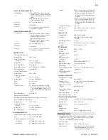
AC Current Input
I
NOM
= 1 A or 5 A secondary depending on the model
Measurement Category:
II
Phase and Neutral Currents
I
NOM
= 5 A
Continuous Rating:
3 • I
NOM
@ 85°C
4 • I
NOM
@ 55°C
A/D Measurement Limit:
217 A peak (154 A rms symmetrical)
Saturation Current Rating: Linear to 96 A symmetrical
1-Second Thermal:
500 A
Burden (per phase):
<0.1 VA @ 5 A
I
NOM
= 1 A
Continuous Rating:
3 • I
NOM
@ 85°C
4 • I
NOM
@ 55°C
A/D Measurement Limit:
43 A peak (31 A rms symmetrical)
Saturation Current Rating: Linear to 19.2 A symmetrical
1-Second Thermal:
100 A
Burden (per phase):
<0.01 VA @ 1 A
AC Voltage Inputs
V
NOM
(kV L-L)/PT Ratio
Range:
100–250 V (if DELTA_Y := DELTA)
100–440 V (if DELTA_Y := WYE)
Rated Continuous Voltage: 300 Vac
10-Second Thermal:
600 Vac
Burden:
<0.1 VA
Input Impedance:
4 M
differential (phase-to-phase)
7 M
common mode (phase-to-chassis)
Power Supply
Relay Start-Up Time:
Approximately 5–10 seconds (after
power is applied until the
ENABLED
LED turns on)
High-Voltage Supply
Rated Supply Voltage:
110–240 Vac, 50/60 Hz
110–250 Vdc
Input Voltage Range
(Design Range):
85–264 Vac
85–300 Vdc
Power Consumption:
<50 VA (ac)
<25 W (dc)
Interruptions:
50 ms @ 125 Vac/Vdc
100 ms @ 250 Vac/Vdc
Low-Voltage Supply
Rated Supply Voltage:
24–48 Vdc
Input Voltage Range
(Design Range):
19.2–60.0 Vdc
Power Consumption:
<25 W (dc)
Interruptions:
10 ms @ 24 Vdc
50 ms @ 48 Vdc
Fuse Ratings
LV Power Supply Fuse
Rating:
3.15 A
Maximum Rated Voltage:
300 Vdc, 250 Vac
Breaking Capacity:
1500 A at 250 Vac
Type:
Time-lag T
HV Power Supply Fuse
Rating:
3.15 A
Maximum Rated Voltage:
300 Vdc, 250 Vac
Breaking Capacity:
1500 A at 250 Vac
Type:
Time-lag T
Output Contacts
General
The relay supports Form A, B, and C outputs.
Dielectric Test Voltage:
2500 Vac
Impulse Withstand Voltage
(U
IMP
):
5000 V
Mechanical Durability:
100,000 no-load operations
Standard Contacts
Pickup/Dropout Time:
8 ms (coil energization to contact
closure)
DC Output Ratings
Rated Operational Voltage: 250 Vdc
Rated Voltage Range:
19.2–275 Vdc
Rated Insulation Voltage:
300 Vdc
Make:
30 A @ 250 Vdc per IEEE C37.90
Continuous Carry:
6 A @ 70°C
4 A @ 85°C
1-Second Thermal:
50 A
Contact Protection:
360 Vdc, 115 J MOV protection across
open contacts


