Assembly
28
04.01|MPG-plus |en
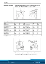
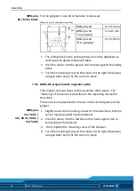
For the grippers in size 64 no fastener is necessary.
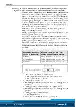
Measures for the sliding block positions
MPG-plus 64
X = 19,2 mm
MPG-plus 64
"I.D. gripping"
X= 34,1 mm
MPG-plus 64
"O.D. gripping"
X = 19,8 mm
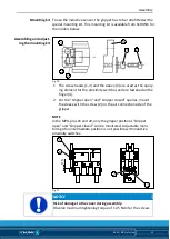
1 The sliding block in the vertical groove has to be displaced ac-
cording to the above-mentioned table.
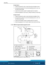
2 Push the sensor into the groove until it bears against the sliding
block.
3 Turn the mounting screw on the sensor to the right (clockwise)
using an Allen key to fix the sensor in place.
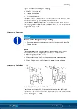
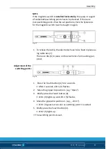
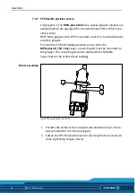
MMS-PI2 programmable magnetic switch
This chapter contains notes on the assembly of the sensor. The
"teaching" of the sensor is described in the operating manual for
the sensor.
The sensor is only destined for the use in the vertical groove of the
gripper.
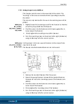
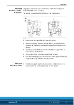
1 Slightly loosen the mounting screws for the fastener so that the
sensor may be pushed into the fastener.
2 Push the sensor into the fastener until it bears against the in-
ternal stop of the fastener.
3 Firmly tighten the mounting screw of the fastener.
4 Turn the mounting screw on the sensor to the right (clockwise)
using an Allen key to fix the sensor in place.
MPG-plus
64 / 64 IS / 64 AS
7.3.6
MPG-plus
32 / 32 AS /
40 / 40 IS / 40 AS /
50 / 50 AS


