Start-up
26
03.00 | MEG 50 EC | Assembly and Operating Manual | en | 389201
Ø
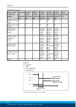
During the movement the digital output "Gripper
stopped" (terminal 13) becomes low.
Ø
The gripper movement can be measured via the output "analog
position output".
Ø
After successful performance of a positioning movement, a High
signal is issued at the "Target-pos. reached" output (terminal 18)
and at the digital output "Gripper stopped" (terminal 13).
Successful performance of the positioning movement means that
the gripper could perform the stroke travel that was specified by
the analog value. If the next travel command is specified, a Low
signal is again issued at the output.
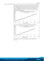
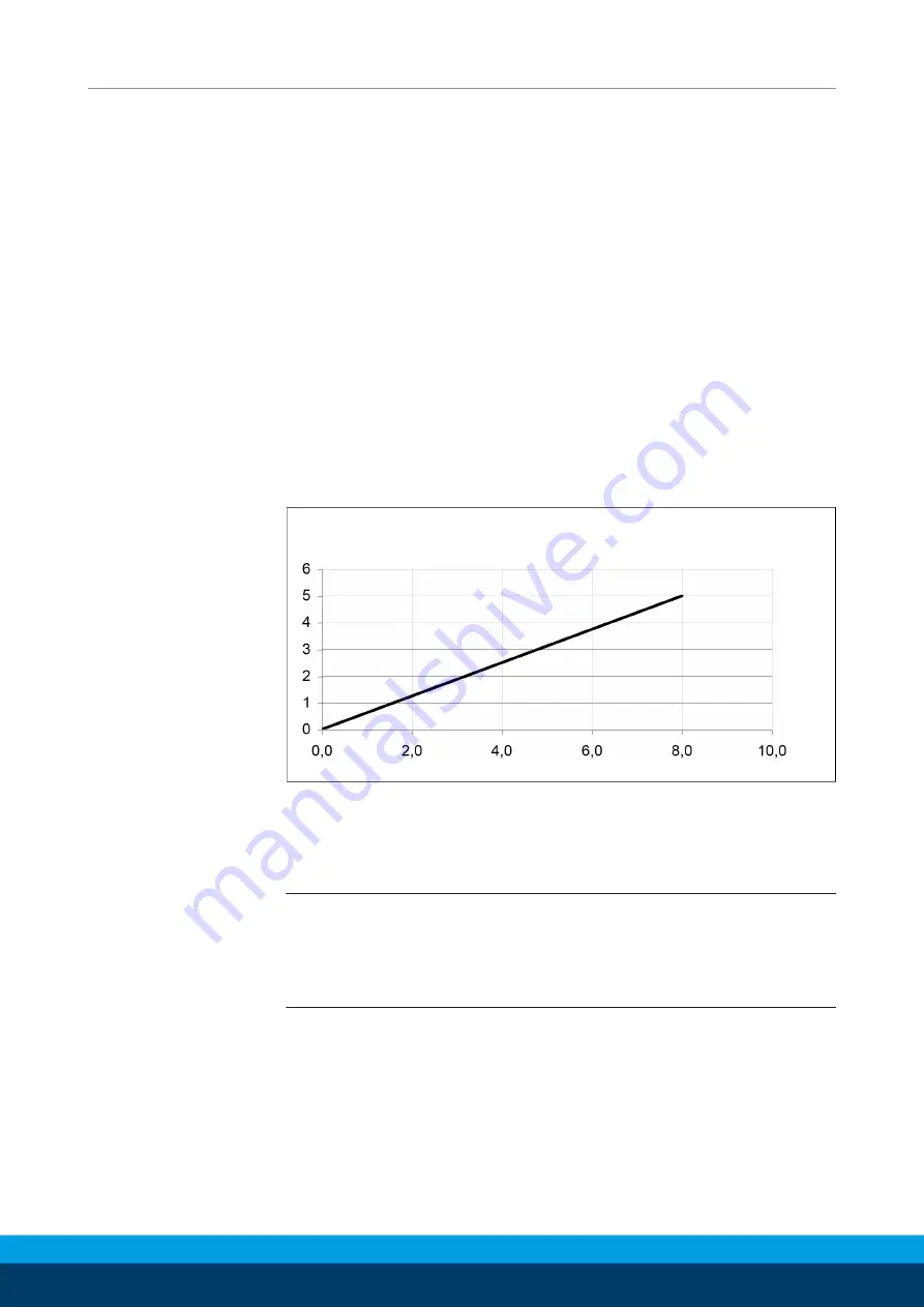
The output "Analog position output" (terminal 15) issues the
current gripper position in the form of an analog value after each
reference run and at any point in time.
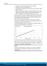
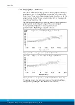
The following diagram shows in which way the output voltage and
the position of the gripper are connected.
Analog position output
Output voltage
in V
Position in mm
Connection between analog position output (terminal 15) and position of the gripper
Note that the position may drift due to step losses. To counter this
drift, we recommend performing another reference run before the
deviation is too large for the application.
NOTE
If precise measurements are necessary, it is recommendable to
adjust the output voltage once (this will not prevent a position
output drift).

