Assembly
14.00 | JGP | Assembly and Operating Manual | en | 389157
21
Ø
OR: Connect compressed air lines to the main air
connections "A" and "B".
✓
Screw in air connections (plug connections).
OR: Screw on throttle valve in order to be able to perform
sufficient throttling and/or damping.
Ø
Screw the product to the machine/system,
21].
✓
If necessary, use appropriate connection elements (adapter
plates).
✓
Observe the maximal tightening torque, admissible screw-in
depth and, if necessary, strength class.
✓
When mounting from the rear or at the side: use cylindrical
pins for fixing the product in place.
Ø
Secure the gripper fingers to the base jaws,
21].
✓
Use centering sleeves from the enclosed accessory pack.
Ø
Connect air purge connection if necessary.
Ø
Connect the sensor, see assembly and operating manual of the
sensor.
Ø
26].
5.2 Connections
5.2.1 Mechanical connection
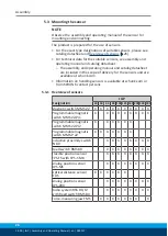
Evenness of the
mounting surface
The values apply to the whole mounting surface to which the
product is mounted.
Requirements for evenness of the mounting surface (Dimensions in mm)
Edge length
Permissible unevenness
< 100
< 0.02
> 100
< 0.05


