background image

Installation

14

02.00 | FT-AXIA 80 EtherCat | Assembly and operating manual | en | 1009369

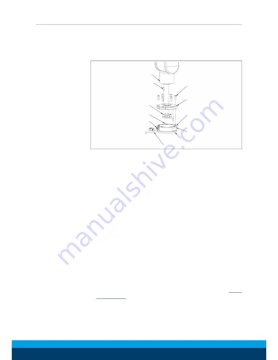
4.3 Installing the Sensor to the Robot

Tools required: 4 mm hex wrench, torque wrench 
Supplies required: Clean rag, Loctite 242® or fasteners with pre-ap-
plied adhesive

Robot

Dowel Pin

(Customer Supplied)

M5 Socket Head 

Cap Screw (6x)

Dowel Pin (2x)

Power and EtherCAT

Connection

Power and EtherCAT cable

(Customer Supplied)

Mounting Side to Customer Tooling

Axia 80

Mounting Side

to Robot or Interface Plate

Interface Plate (example)

Mounting Fasteners

(Customer Supplied)

Ø

To attach the mounting adapter plate to the robot, remove the
six M5 socket head cap screws that secure the adapter plate to
the mounting side of the Axia80 sensor.

Ø

Ensure the mounting surface of the mounting adapter plate and
robot are clean and free of debris.

Ø

If applicable, secure the mounting adapter plate to the robot
arm with customer supplied fasteners and dowel pin.

Ø

M5x 12 socket head cap screws class 12.9 (6x), with pre-applied
adhesive require no additional Loctite for initial installation.
When reusing fasteners, always apply Loctite 242 to the M5
socket head cap screws.

Ø

Using a 4 mm hex wrench, secure the sensor to the mounting
adapter plate with the six M5x 12 socket head cap screws, class
12.9. Tighten to 9 Nm.

Ø

Once the sensor is installed on the robot, the customer tooling
or tool interface plate can be installed. 

NOTICE! The tool must not touch any other part of the sensor
except the tool side; otherwise, the sensor will not properly
detect loads.

Ø

Connect a power and EtherCAT cable from the sensor’s connec-
tion to the customer application.

Ø

Properly restrain and route the power and EtherCAT cable 

Rout-

ing the Cable

 [

}

 12].

Ø

After installation is complete, the sensor is ready for normal op-
eration.

Содержание FT-AXIA 80 EtherCat

Страница 1: ...Original manual Assembly and operating manual FT AXIA 80 EtherCat FT Sensor...

Страница 2: ...ke alterations for the purpose of technical improvement Document number 1009369 Version 02 00 08 01 2019 en SCHUNK GmbH Co KG All rights reserved Dear Customer thank you for trusting our products and...

Страница 3: ...14 4 4 Removing the Sensor from the Robot 15 4 5 Pin Assignment for the EtherCAT and Power Connection 15 5 Operation 16 5 1 Sensor Enviroment 16 5 2 Sample Rate 16 5 3 Low pass Filter 17 6 EtherCAT Bu...

Страница 4: ...rom the robot manufacturer and or the manufacturers of other com ponents used in the installation DANGER Danger for persons Non observance will inevitably cause irreversible injury or death CAUTION Da...

Страница 5: ...rranty Use the supplied mounting adapter plate and the provided tool side mounting bolt pattern to mount the sensor to the ro bot and customer tooling to the sensor Refer to Drawings 29 for more infor...

Страница 6: ...o 85 Operating Temperature C 0 to 65 Electrical Specifications Power Source DC Power Voltage V min max 12 30 Maximum Power Consumption W 1 The power supply input is protected from a reversed polarity...

Страница 7: ...ting side attaches to a mounting adapter plate which mounts to the customer robot The tool side attaches to the cus tomer tooling Both the mounting and tool sides have a 71 12 mm bolt circle pattern w...

Страница 8: ...ne second for each LED 2 Run Red 3 EtherCAT Link Activity Red 4 Sensor Status Green 5 EtherCAT Link Activity Green The Green Run LED is not tested in the self test sequence 3 1 2 EtherCAT Link Activit...

Страница 9: ...h status of the sensor as follows LED State Description Off No power Green Normal operation The sensor s electronics are func tioning and communicating Flashing green Power up self testing At power up...

Страница 10: ...d void the warranty Use the supplied mounting bolt pattern and the provided tool side mounting bolt pattern to mount the sensor to the robot and customer tooling to the sensor Drawings 29 NOTICE Using...

Страница 11: ...he sensor s tool side attaches to the customer tooling If adapter plate s are required to interface the sensor to the robot arm and customer tooling SCHUNK can supply custom robot and tool ad apter pl...

Страница 12: ...ceed length requirements crea te a gap between the interfacing surfaces and cause damage The adapter plate s must not distort from the maximum force and torque values that can be applied to the sensor...

Страница 13: ...ge to equipment Dam age to the sensor or cable from improper routing will void the warranty The cable must withstand the repetitive motions of the robot without failing The electrical line especially...

Страница 14: ...are clean and free of debris If applicable secure the mounting adapter plate to the robot arm with customer supplied fasteners and dowel pin M5x 12 socket head cap screws class 12 9 6x with pre applie...

Страница 15: ...e the customer supplied screws that attach to the customer tool ing to the sensor Supporting the sensor use a hex wrench to loosen the six M5 socket head cap screws that secure to the sensor to the mo...

Страница 16: ...Ensure the cable jacketing is in good condition to prevent transducer damage NOTE Transducers may react to exceptionally strong and changing elec tromagnetic fields such as those produced by magnetic...

Страница 17: ...ndent on the sample rate selection which is defined in Sample Rate 16 The cutoff frequencies for the dif ferent sampling rates are listed in the following table and graphs Selected Filter 3dB Cutoff F...

Страница 18: ...erCat Assembly and operating manual en 1009369 Attenuation Frequency Filter Attenuation at 1 kHz Sample Rate Attenuation Frequency Filter Attenuation at 2 kHz Sample Rate Attenuation Frequency Filter...

Страница 19: ...Change the sample rate 6 1 PDO Interface The PDO interface exchanges data in real time with the F T sensor TxPDO Map Output Data The TxPDO combines Object 0x6000 Reading Data 23 Ob ject 0x6010 Status...

Страница 20: ...num ber e g SI 120 95 0x03 Calibration Family STRING 8 Always reads ECAT 0x04 Calibration Time STRING 30 The date the sensor was calibrated 0x05 through 0x2e Reserved DINT Reserved 0x2f Force Units U...

Страница 21: ...sitive All time peak positive force torque loads 0x58 PeakLoadsPosFy 0x59 PeakLoadsPosFz 0x5a PeakLoadsPosTx 0x5b PeakLoadsPosTy 0x5c PeakLoadsPosTz 0x5d PeakLoadsNegFx DINT Peak Loads Negative All ti...

Страница 22: ...wing Table Errors in the Diagnostic Readings Status Message Priority Text Error Messages 1 Supply voltage out of range 2 Gage temperature out of range 3 Calibration checksum error 4 Gage s disconnecte...

Страница 23: ...or UNIT Major Version 0x02 Minor UNIT Minor Version 0x03 Revision UNIT Revision 0x04 Boatloader Version UDINT Bootloader Version 6 2 4 Object 0x6000 Reading Data This read only object represents the c...

Страница 24: ...es breaks this error bit is set active This bit remains set until a power cycle Yes 3 Busy Bit The sensor is performing 1 or more of the following activities that may temporar ily affect the F T data...

Страница 25: ...ing Yes 29 Calibration checksum error This bit is set if the active calibration has an invalid checksum Yes 30 Sensing Range Exceeded1 This bit is set whenever a F T reading exceeds the calib rated ra...

Страница 26: ...Bit Function 0 1 Set bias against current load 0 Use last set bias 1 Clear Monitor Condition 0 1 clear 2 leave alone 2 1 clear bias 0 leave bias unchanged 3 Reserved 4 7 The low pass filter selection...

Страница 27: ...AXIA 80 Ethernet is IP64 rated and must be kept free of mois ture Debris and dust should be kept from accumulating on or in the sensor 7 2 Periodic Calibrating Periodic calibration of the sensor and...

Страница 28: ...e for the Axia80 sensor has little to no noise superimposed The sensor should be grounded through installation construction Drift After a load is removed or applied the raw gage reading does not stabi...

Страница 29: ...damage transducer and will void the warranty 3 Do not exceed interface depth may cause incorrect readings 4 For best accuracy transducer must be mounted to a surface rigid enough to support loads wit...

Страница 30: ...urpose input output I2C Inter integrated circuit IP64 Ingress protection rating 64 desig nates protection against dust and splashing water on all sides ISR Interrupt service routine MAP The Mounting A...

Страница 31: ...NG 30 A data type representing 30 charac ters using 30 bytes STRING 8 A data type representing 8 charac ters using 8 bytes UINT A 16 bit data type representing an un signed integer USINT An 8 bit data...

Страница 32: ...32 02 00 FT AXIA 80 EtherCat Assembly and operating manual en 1009369...

Отзывы: