background image


Translation of the original manual 


Compensation unit 

AGE-F-XY 31-80 

Assembly and Operating Manual 


Superior Clamping and Gripping 


Содержание AGE-F-XY 31-80

Страница 1: ...Translation of the original manual Compensation unit AGE F XY 31 80 Assembly and Operating Manual Superior Clamping and Gripping...

Страница 2: ...02 23 01 2017 en SCHUNK GmbH Co KG All rights reserved Dear customer congratulations on choosing a SCHUNK product By choosing SCHUNK you have opted for the highest precision top quality and best servi...

Страница 3: ...5 Accessories 10 5 1 Sensors 10 6 Technical data 11 7 Assembly and settings 12 7 1 Assembly example 12 7 2 Mechanical connection 13 7 3 Setting the stop in order to limit stroke 14 7 4 Adjusting remov...

Страница 4: ...r Basic safety notes Warnings The following key words and symbols are used to highlight dan gers Key words DANGER Dangers for persons Non compliance will inevitably cause irreversible injury or death...

Страница 5: ...en 5 Applicable documents General terms of business Catalog data sheet of the purchased product Assembly and Operating manuals of the accessories The documents marked with an asterisk can be download...

Страница 6: ...manual and to comply with the maintenance intervals Not intended use It is not intended use if the product is used for example as a pressing tool stamping tool lifting gear guide for tools cutting to...

Страница 7: ...constructional changes Attachments and modifications constructional changes and sub sequent work e g additional threads drill holes and safety devic es may impair the operation and safety or damage th...

Страница 8: ...ge and experience qualified personnel is able to perform the delegated tasks recognize and avoid possible dangers and knows the relevant standards and reg ulations Instructed persons were instructed b...

Страница 9: ...e modifications and additions outside the danger zone Secure the product during all operations against uncontrolled activation Take a precautionary approach by maintenance and disassembly Only special...

Страница 10: ...rt of the warranty Scope of delivery The scope of delivery includes Compensation unit with spring return AGE F XY in the version ordered Accessories A wide range of accessories are available for this...

Страница 11: ...0 200 300 2800 Max payload load capacity F pressure N 200 500 3000 12000 Weight kg 0 123 0 23 0 78 3 13 Max return force N Version 1 Version 2 Version 3 2 0 3 5 7 0 3 0 5 0 7 0 20 0 32 0 45 0 70 0 130...

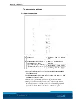
Страница 12: ...mpensation element 5 Handling device e g gripper 6 Mounting screws for gripper An interface plate with a hole pattern for locating holes is op tionally available The adapter plate is screwed with the...

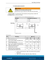
Страница 13: ...ly Mounting material Item Mounting AGE F XY 31 40 63 80 Y Thread diameter and max screw in depth Y tool side mm M2 5x7 M3x8 M4x8 M5 M6x 10 X Thread diameter and max screw in depth X tool side mm M3x5...

Страница 14: ...tting the stop in order to limit stroke Setscrew 52 to limit stroke for AGE F XY 40 Setscrew 52 to limit stroke for AGE F XY 63 80 Dimensions of setscrew 52 Item Designation AGE F XY 40 63 80 52 Threa...

Страница 15: ...can fall into the housing if it is screwed in too far The compensation unit may jam Observe the minimum length of the setscrew 1 Remove the setscrew 52 using a hexagon socket wrench NOTE Limiting the...

Страница 16: ...rewed in too far this will cause the unit to jam springs on block This can be recognized if the unit is no longer performing the complete stroke or is no longer moving Setting dimension for the setscr...

Страница 17: ...cing return springs for units built beginning in June 2016 The unit comprises 4 compression springs for the return position function As of June 2016 the unit s spring force values can no longer be ad...

Страница 18: ...ter plate made of ordinary steel At ferromagnetic adapter plates The module must firstly be mounted on the adapter plate Then the positions of the magnetic switch have to be set NOTE Do not use the se...

Страница 19: ...gnetic switch stop position A The MMS magnetic switches are mounted and adjusted equally for each axis movement Assembly instructions 1 Screw in the sensor OR Insert sensor axially into the groove unt...

Страница 20: ...ring adjustment screwed in too far Turn back the setscrew 50 7 4 Page 16 Magnetic switch MMS does not work cannot be adjusted Possible cause Corrective action Steel screws used for fastening the compe...

Страница 21: ...ng to possible product damage Reduce the lubricant intervals accordingly Interval Mio cycles 2 Lubricants Lubrication points basic lubrication SCHUNK recommends the lubricants listed During maintenanc...

Страница 22: ...e housing 1 off the module 6 Undo setscrews 51 52 on the housing top 2 7 Remove screws 30 from the housing top 2 8 Lift the top of the housing 2 off the guide cross 3 9 Remove screws 5 to separate the...

Страница 23: ...Page 21 Oil or grease bare external steel parts Der Zusammenbau erfolgt in umgekehrter Reihenfolge zum Zerle gen Dabei Folgendes beachten Unless otherwise specified secure all screws and nuts with Lo...

Страница 24: ...rawing 24 02 02 AGE F XY 31 80 en Assembly drawing The following figure is an example image It serves for illustration and assignment of the spare parts Variations are possible depending on size and v...

Отзывы: