background image

Manual

LS101 / LSW101 

Schulte-Schlagbaum AG 

Page  38 of 39 

 LS(W)101_6-703-2 30R1 4_EN.DOCX

Configuration and user behaviour 

The  configuration  (release  time,  status  display  etc.)  and  the  user  behaviour  impact  on  the  battery  life  of  the 
locking system. Refer to the relevant sections in the guides for details on this topic. 

Battery management 

The  electronic  locking  systems  in  the  SAFE-O-TRONIC

®

  access  LS(W)101  range  are  fitted  with  integrated 

battery management with an optical low-battery signal to indicate that the battery requires replacement. Refer 
to the relevant guides for details on this topic. 

Information on battery replacement 

The  point  at  which  the  SAFE-O-TRONIC

®


access 

battery  pack  must  be  replaced  depends  on  how

often the  locking system was activated, or  how long the  battery  pack has been installed, and  on the
ambient temperature in which the locking system is operated.

Due  to  slight,  yet  unavoidable,  self-discharge  of  the  batteries  it  may  be  necessary  to  replace  the
battery pack before the number of activations indicated has been reached.

There is a risk of injury through improper handling of the batteries.

On the LSW101, the batteries can only replaced with the door open. A function check after replacing a
battery should always be performed with the door open.

Installation and battery replacement must only be performed by trained specialists in accordance with
these operating and installation instructions.

Only use battery packs sold by Schulte-Schlagbaum.

Do not allow the battery to reach temperatures in excess of the recommended storage temperature.

Ensure that the polarities are correct when inserting the batteries. (LSW101 battery holder)

Always replace discharged batteries with new batteries.

Battery packs may not be charged.

Disposal 

Recycle defective or used battery packs according to European Directive 2006/66/EG. 
Observe local regulations concerning the disposal of batteries. 


Содержание SAFE-O-TRONIC access LS101

Страница 1: ...Manual SAFE O TRONIC access LS101 LSW101 Cabinet Lock English D E Architectural Hardware Ltd 17 Royce Road Carr Road Ind Est Peterborough Cambs PE1 5YB www DandE co uk ...

Страница 2: ...mplete information Mistakes can never be prevented entirely despite all the effort taken and so we appreciate when mistakes are pointed out to us SAFE O TRONIC is a registered trademark of Schulte Schlagbaum AG Safety information and warnings This guide describes commissioning and operation of a SAFE O TRONIC access LS W 101 furniture lock The device may only be used for the purpose intended by th...

Страница 3: ...rview 18 Usage duration overview 18 Changing the usage duration 19 LS W 101 functions 20 LS W 101 overview of settings 20 Changing the LS W 101 settings 21 Information 22 LED display 22 Troubleshooting 23 Battery replacement 23 Battery monitoring Battery alarm 24 LS101 installation 25 Installation direction 25 LS101 installation notes 26 Preparing the door for LS101 installation 27 Installation 27...

Страница 4: ...sing the Abort key clears the PIN Code input and aborts the current process Keys 1 2 3 4 5 6 7 8 9 0 Number keys for PIN code entry Note Programming is initiated with the following key combination Press the OK and Abort keys at the same time 1 2 3 4 5 6 7 8 9 0 LED display Replaceable identification plate Rotary knob Capacitive keypad LS101 LSW101 ...

Страница 5: ...In the event of a pause of more than three seconds between pressing of individual keys the entire entry is cancelled Protection against tampering Level 1 The user has a maximum of five tries to enter the right PIN code After the fifth incorrect entry every further entry is blocked for one minute to ensure tampering protection This block time of one minute is indicated by the red LED flashing Level...

Страница 6: ...ion check of the SAFE O TRONIC access LS W 101 Once installed test the locking function of the SAFE O TRONIC access LS W 101 using the Test Code In particular ensure ease of movement of the lever or bolt during locking and unlocking Installation under tension can result in malfunction Locking and unlocking using the Test Code Press the 0 key Then press the OK key The rotary knob can be actuated fo...

Страница 7: ...aster Code You can change the Master Code at any time Master Code cannot be programmed using a leading 0 Programming the Master Code in factory setting Press the OK and Abort key at the same time Enter your Master Code Press the OK key Enter your Master Code again for verification Press the OK key to complete the process Note After programming the Master Code mode 147 is automatically activated Mo...

Страница 8: ...S W 101 can be unlocked or locked with the active Master Code at any time Example LS101 Enter the active Master Code Then press the OK key Turn the rotary knob Note If an unlocked LS W 101 is locked with a Master Code this LS W 101 can then only be unlocked with the Master Code In modes 1x8 4x8 and 4x9 the Master Code cannot be used for locking Note This guide only uses example PIN codes Please us...

Страница 9: ...ctive Master Code Press the OK and Abort keys at the same time Enter a new Master Code Press the OK key Enter the new Master Code again Press the OK key Note This guide only uses example PIN codes Please use your own PIN codes for your locking system Note If you have forgotten the Master Code a Master Reset is required In this case please contact our support Master Code guidelines You can choose a...

Страница 10: ...Fixed cabinet assignment fix The LS W 101 locking system is configured so that a user is assigned a cabinet as well as a PIN to lock the cabinet by the system operator With fixed cabinet assignment up to ten different user PINs can be programmed OK key To confirm the entered user PIN there are modes with or without OK key to lock or unlock a cabinet Number of digits for the User PIN The User PIN c...

Страница 11: ...xamples on entering modes Note After initially programming the furniture locking system mode 147 free cabinet selection 4 digit with OK key is set by default Free free Fixed fix User PIN length One open All open Description PIN Code to set the mode 4 5 6 X X X With OK key 1 X 7 X X X Without OK key 1 X 8 X X X Lock with OK key 1 X 9 X X X With OK key 2 X 7 X X X Without OK key 2 X 8 X X X Lock wit...

Страница 12: ...ked The following describes how to enter a new mode Example Mode 148 Press the OK and Abort keys at the same time Enter the active Master Code Press the OK and Abort keys at the same time Enter new mode Press the OK key Enter new mode again Press the OK key Note The mode can only be changed when the lock is unlocked When changing the mode all User PINs entered in fixed cabinet assignment modes are...

Страница 13: ...es The length of the PIN code 4 5 or 6 digit depends on the selected mode Mode 147 Free cabinet selection 4 digit PIN with OK key Enter 4 digit PIN Press the OK key Enter 4 digit PIN Press the OK key Mode 268 Fixed cabinet assignment 6 digit PIN without OK key one open Enter 6 digit PIN Enter 6 digit PIN 1 3 5 5 1 3 5 5 1 3 5 5 1 3 5 5 1 5 1 5 ...

Страница 14: ... the OK key Enter 5 digit PIN Mode 448 Fixed cabinet assignment 4 digit PIN lock without OK key all open This mode can only be used with the LS101 variant Turn knob to lock position Enter 4 digit PIN Note This guide only uses example codes Please use your own PIN codes for your locking system Note The mode can only be changed when the lock is unlocked 1 3 5 7 3 1 3 5 7 ...

Страница 15: ...u can configure which users are permitted to unlock the locked cabinet In the one open setting only the user who locked the cabinet can unlock it All open In fixed cabinet assignment mode you can configure which users are permitted to unlock the locked cabinet In the all open setting all programmed users can unlock the locked cabinet no matter who locked it ...

Страница 16: ...ple Mode 247 fixed cabinet assignment four digit with OK key one open Enter three User PINs 7458 8488 and 1181 Press the OK and Abort keys at the same time Enter the active Master Code Press the OK and Abort keys at the same time Enter the User PIN Press the OK key Enter the User PIN Press the OK key Enter the User PIN Press the OK key Note User PINs can only be entered when the lock is unlocked A...

Страница 17: ...dividual User PINs from the lock The following describes how to delete all User PINS Example Deleting all User PINs Press the OK and Abort keys at the same time Enter the active Master Code Press the OK and Abort keys at the same time Enter the delete PIN Press the OK key Enter the delete PIN again Press the OK key Note All User PINs in your lock are deleted Afterwards you can enter up to ten diff...

Страница 18: ...binet is opened using the Master Code you have to enter a new PIN to use it again depending on the mode Setting the usage duration The usage duration starts after the lock is locked The usage duration can be configured from one time unit up to 99 time units The usage duration function is disabled by default and the hour is set as time unit Time unit overview The available time unit settings are li...

Страница 19: ...locked The following describes how to enter a new usage duration Example Usage duration 705 The lock unlocks automatically after 5 time units Press the OK and Abort keys at the same time Enter the active Master Code Press the OK and Abort keys at the same time Enter a new usage duration Press the OK key Enter the new usage duration again Press the OK key Note The usage duration can only be changed...

Страница 20: ...r is open or closed In unsuitable cabinet constructions the sensor system can cause malfunctions In such cases the door recognition query can be disabled When the door recognition query is disabled the alarm function is no longer available Alarm In combination with the door status query for locked cabinets it is possible to emit an alarm signal in case of unauthorised break in The alarm signal LED...

Страница 21: ... is unlocked The following describes how to set LED status display for the LSW101 Example LSW101 setting 911 LED status signal on when door is closed Press the OK and Abort keys at the same time Enter the active Master Code Press the OK and Abort keys at the same time Enter new LSW setting Press the OK key Enter new LSW setting again Press the OK key Note The LSW101 settings can only be changed wh...

Страница 22: ... incorrect code was entered five times 0 2 seconds Key input 0 5 seconds Error or Abort key X was pressed LEDs flash twice Handling error the rotary knob was not actuated within the release time Flashing Rotary knob actuation expected 1 second LS W 101 was locked programming successful 2 seconds LS W 101 was unlocked 0 5 seconds Code was accepted 3 seconds Internal function fault LS W 101 must be ...

Страница 23: ...d remove the battery pack Disconnect the two pin connector of the battery pack 3 Connect the new battery pack to the connector and insert it into the LS101 using the battery replacement tool 4 Close the battery compartment and fasten the screw again LSW101 1 Loosen the bottom screw in the cover with a TX20 screwdriver 2 Open the top and bottom covers and remove the battery pack Disconnect the two ...

Страница 24: ...he battery voltage is too low This is indicated by an advance warning in the form of three simultaneous flashes of all LEDs In this case quick replacement of the battery is recommended If the battery is not replaced a battery alarm is activated after a certain time This is indicated by three alternative flashes of the red and green LEDs The battery must now be replaced In this state the LSW can on...

Страница 25: ...r different installation directions Note This guide uses installation direction A for its examples The LS101 furniture locking system must be ordered for the correct installation direction The installation direction cannot be changed later on Installation direction A rotary knob up Installation direction B rotary knob down Installation direction C rotary knob left Installation direction D rotary k...

Страница 26: ... 4 Locking levers depending on the cabinet type a cranked or hooked locking lever can be used 5 Fixing screws SW10 for the locking lever 6 Sleeve to fasten the LS101 on the door door thicknesses 10 mm to 20 mm 7 Sleeve to fasten the LS101 on the door door thicknesses from 1 mm to 10 mm 8 Screws TX20 to fasten the LS101 on the door 9 Rotary knob Note The locking lever 4 must be held secured when ti...

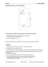
Страница 27: ...d using a hole pattern Installation 1 Insert the LS101 1 in the two holes 19 1 mm 16 mm and 7 mm 2 Fasten the LS101 1 with the nuts 2 3 Attach the LS101 1 with the screw 8 and sleeve 6 or 7 depending on the door thickness 4 Fasten the washer 3 to set the direction of rotation and locking lever 4 by means of the fastening screw 5 see note on page 6 5 Test the functioning of the LS101 via Test Code ...

Страница 28: ...ocking 1 LS101 labelled with direction of rotation left for locking 2 Washer that is inserted on the LS101 inside the door The L recess faces downward 3 Back of the LS101 onto which the washer is inserted To mount the LS101 in a position where the rotary knob is not facing upward e g horizontal mounting the washer has to be turned accordingly If you want to turn the rotary knob clockwise right ins...

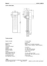
Страница 29: ...sing dimensions incl Rotary knob L x W x D Housing frame colour Control panel colour Door thickness 20 mm 2 x green LEDs 2 x red LEDs Beeper Battery pack 3 x Alkaline cells AAA approx 3 years or approx 30 000 activations 0 to 60 C 15 C to 70 C 10 90 non condensing for protected inside area approx 300 g 151 mm x 38 mm x 33 mm similar to RAL 9006 white aluminium black or white 1 to 18 mm 20 mm Note ...

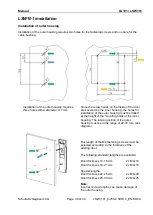
Страница 30: ... the inner housing the holes for installation of the outer housing must be drilled at the height of the mounting holes of the inner housing The lateral position of the outer housing must be in the range of 22 72 mm see diagram The length of the M4 fastening screws must be selected according to the thickness of the existing door The following standard lengths are available Door thickness 10 15 mm 2...

Страница 31: ...imum screw in depth of 6 mm Installation of the inner housing requires four M5 screw threads After installation of the outer housing the 6 pin connecting cable must be pushed through the opening of the inner housing The inner housing is then tightened using four screws After fastening of the inner housing the 6 pin connecting cable must be plugged onto the 6 pin connector on the board Finally the ...

Страница 32: ... and a maximum 8 mm on the side of the active bolt Information on the sensing slide The sensing slide indicates the status of the door irrespective of the bolt position This status is required for door monitoring and alarm messages amongst other things The functionality of the sensing slide can be configured Please refer to the programming software guide for information on configuration options Vi...

Страница 33: ...est should be performed when the door is open The sensing slide is not active in the factory pre set state A locking operation can consequently be carried out with the Test Code even when the door is open The bolt is motor driven To be able to ensure proper functioning the bolt must move smoothly when the door is closed Should this not be the case the door must be aligned The door must be flush wi...

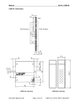
Страница 34: ...Manual LS101 LSW101 Schulte Schlagbaum AG Page 34 of 39 LS W 101_6 703 2 30R1 4_EN DOCX LSW101 dimensions Door Outer housing Inner housing LSW inner housing LSW outer housing ...

Страница 35: ...ge 15 C to 70 C Relative humidity 10 90 non condensing Enclosure protection according to DIN EN 60529 Inner housing For protected inside area Outer housing IP 65 Weight approx 300 g Housing dimensions Outer housing 156 5 x 41 4 Inner housing 120 mm x 110 mm x 31 5 mm Housing frame colour similar to RAL 9006 white aluminium Control panel colour black or white Inner housing colour black Door thickne...

Страница 36: ...nts and disinfectants Abrasive cleaning agents acids or alkaline solutions may not be used when carrying out maintenance Likewise pressure cleaners may not be used Hosing down of the LS W 101 may result in destruction and exclusion of liability Identification plate replacement The old identification plate can be removed from the LS W 101 by inserting a small screwdriver into the centre of the plat...

Страница 37: ...00 activations LSW101 Standard battery pack Alkaline manganese 3xLR06 AAA Article number 38450901 Battery life approx 5 years or approx 55 000 activations Battery holder for 3xLR06 AA Article number 38450902 Batteries for the battery holder must be provided on site Claims concerning the battery life can therefore not be made Battery recommendation Alkaline manganese Panasonic Powerline The followi...

Страница 38: ...e locking system is operated Due to slight yet unavoidable self discharge of the batteries it may be necessary to replace the battery pack before the number of activations indicated has been reached There is a risk of injury through improper handling of the batteries On the LSW101 the batteries can only replaced with the door open A function check after replacing a battery should always be perform...

Страница 39: ...s in the defined temperature range Installation and battery replacement may only be carried out by trained expert personnel in accordance with the instructions Only use battery packs sold by SAG Do not charge short circuit open or heat battery packs Old or used battery packs must be disposed of properly Keep battery backs out of reach of children The instructions should be handed over by the perso...

Отзывы: