18
EN
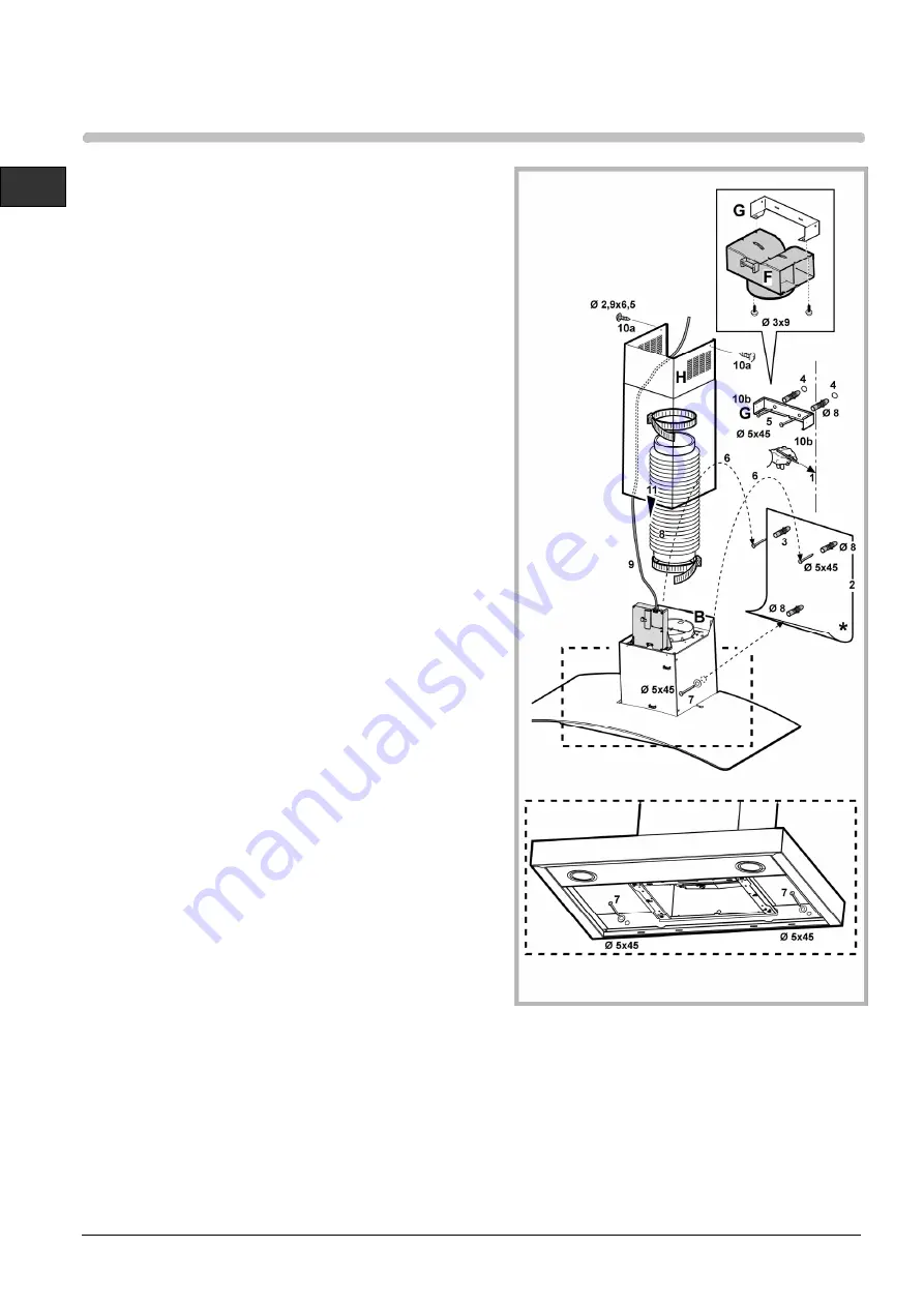
1. Drawing a line on the wall with a pencil up to the
ceiling, corresponding to the centre line, will make
the installation operations easier.
2. Apply the perforation diagram to the wall: the
vertical centre line printed on the perforation
diagram should correspond to the centre line drawn
on the wall. In addition, the lower edge of the
perforation diagram corresponds to the lower edge
of the hood.
3. Make holes as indicated on the template, insert the
wall dowels and screw 2 screws into the upper
holes, leaving a space of about 1 cm between the
head of the screw and the wall.
Note: Always make the holes indicated on the
template. The upper 2 are for hooking the hood up
while the lower holes (generally 1 central or more
lateral) are for the definitive and safety fixing.
4. Apply flues support bracket „G“ to the wall touching
the ceiling. Use the flues support bracket as a
perforation diagram (the small slot in the support
must coincide with the line previously drawn on the
wall, if present), and mark two holes with a pencil.
Make the holes and insert 2 dowels.
5. Fix the flues support bracket to the wall with 2
screws.
6. Hang the hood to the two upper screws (see
installation phase 3).
7. Introduce and screw the screws (and washer(s)) up
into the hole(s) for the definitive fixing
(COMPULSORY!!). Then, having checked the
setting of the hood, TIGHTEN ALL THE upper and
lower SCREWS.
Note: the lower fixing points are visible removing the
fats filters and they are at the sides and/or at the
centre of the hood (after having removed the frame
of the carbon filter, if present, in the latter case).
In any case, we recommend using the lateral holes,
when available, to increase the stability of the hood.
8. Connect a tube (tube and bands for fixing not
supplied, to be purchased) for discharging the
fumes to the connection ring placed over the
aspiration motor unit.
The other end of the tube should be connected to a
device for expelling fumes on the outside of the
hood in the aspiration version. If you want to use the
filtering version, fix deflector F to flues support
bracket G and connect the other end of the tube to
the connection ring placed on deflector F.
9. Connect the electricity.
10. Apply the flues and fix them above with 2 screws
(10a) to flues support bracket „G“ (10b).
11. Slide the lower section of the flue down to cover the
aspiration set until inserting it completely into the
apposite housing over the hood.
Remount the carbon filter frame and the fat/s filter/s
and check the perfect functioning of the hood.


