

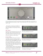


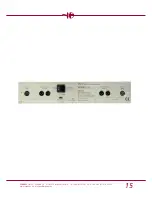


The Signal Path and Operating Controls
6
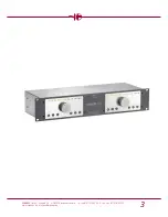
SCHOEPS
GmbH · Spitalstr. 20 · D-76227 Karlsruhe (Durlach) · Tel: +49 (0)721 943 20-0 · Fax: +49 (0)721 495 750
www.schoeps.de · [email protected]
whenever phantom powering is turned on
or off, as indicated by a red LED in the
”Mute” switch.
The status of the ”P48” switch is automat-
ically stored. When the preamplifier is turned
on, phantom powering will be activated if it
was on when the unit was last turned off.
Note:
When phantom powering is turned
on, pins 2 and 3 of the respective input socket
will carry 48 Volts DC. If this should be con-
nected to a line-level input, damage can be
caused.
Mute Switch
The output of each channel can be muted
for any length of time by pressing its Mute
switch. The switch is illuminated in red as long
as this function remains activated. The status
of this function is automatically stored when
the preamp is powered off.
Polarity Switch
When recording with multiple microphones,
e.g. miking percussion such as a snare drum
from above and below simultaneously, signal
cancellation can occur due to the conflicting
phase relationships. Problems can also occur
when microphone or cable connectors are
incorrectly wired.
A simple test (and also a solution) is pro-
vided by the ”Polarity” switch, which allows
the user to invert the signals of the corre-
sponding channel.
When activated, the LED in the switch will
glow brightly.
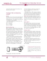
balanced
micro-
phone
output
VSR 5 input socket
The plug housing should not be connected to
the cable shield (pin 1)
, since this can cause a
ground loop. For best protection from electro-
magnetic disturbance we recommend the use
of
SCHOEPS
' special XLR-3 cable, e.g. K EMC 10 U
(10 meters
).
+phase
-phase
screen
unit must be returned to the factory or its
warranty will be voided.
The Signal Path and Operating
Controls
Inputs
The XLR sockets of the electronically balanced
inputs are on the unit's rear panel, labeled
”Balanced Input”. The inputs accept balanced
or unbalanced audio signals.
The contact assignment follows the inter-
national standards:
Pin 1 = Ground
Pin 2 = (+) Phase
Pin 3 = (-) Phase
Phantom Powering
Most condenser microphones require phan-
tom powering in order to operate. The VSR 5
supplies this at its inputs. It can be turned
on and off with the front panel ”P48” switch.
The open-circuit voltage is 48 Volts in keep-
ing with international standards, provided
via a pair of 6.8 k
Ω
resistors on pins 2 and 3
of the input sockets.
In most conventional microphone pream-
plifiers, turning the phantom powering on
or off causes a change in low-frequency
voltage at the output, which can be audible
as a loud noise, and can cause harm to
other equipment. In the
SCHOEPS
VSR 5 an
automatic muting circuit avoids this prob-
lem. The circuit activates for 2.5 seconds
1
2
3
X
Connecting to the inputs of the VSR 5


