


5
Introduction / The Power Supply
SCHOEPS
GmbH · Spitalstr. 20 · D-76227 Karlsruhe (Durlach) · Tel: +49 (0)721 943 20-0 · Fax: +49 (0)721 495 750
www.schoeps.de · [email protected]
Two independent outputs, each with its own
circuitry, are provided for each channel.
Behind the robust aluminum front panel,
the chassis is stainless steel which guarantees
high mechanical stability and resistance to
environmental influences. It also shields the
circuitry from electrical and electromagnetic
fields.
The Power Supply
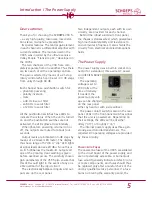
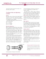
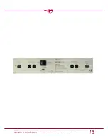
The power supply uses a built-in socket con-
nector for a standard, three-wire AC power
cord (IEC/EN 60320
C14).
The operating
voltage is set to
230 Volts at the
time of delivery.
If needed, the
power supply volt-
age can be changed
on the rear panel
either by hand or with a screwdriver.
The power on/off switch is also on the rear
panel. LEDs in the front-panel switches signal
that the unit is powered on. Depending on
their settings, the LEDs will be lit either
dimly (”off”) or brightly (”on”).
The internal power supply uses three gen-
erously-sized toroidal transformers. The
required DC operating voltages are provided
by linear circuitry.
Power-Line Fuses
The power-line fuses of the VSR 5 are soldered
to the circuit board of the power supply, and
are not externally accessible. A burned-out
fuse would generally indicate a defect in one
or more components, and fuses should thus
be replaced only after a careful check of the
unit by qualified service personnel. If a fuse
burns out during the warranty period, the
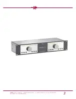
Dear customer,
Thank you for choosing the
SCHOEPS
VSR 5
– a very high-quality, low-noise, low-distor-
tion stereo microphone preamplifier.
Its special features: The central gain element
in each channel is a differential amplifier with
current feedback. The module used in the
VSR 5 was inspired by the ultra-low-noise
Valley People ”Trans-Amp LZ,” developed in
the 1970s.
The two channels of the VSR 5 are com-
pletely separate from one another. Thus there
are two each of all the operating controls.
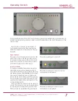
The gain is selected by means of a 21-step
rotary control which can be set in 3 dB steps
from unity through 60 dB.
Each channel has a pushbutton switch for:
– phantom powering
– polarity inversion
– mute
– a 40 Hz low-cut filter
– an 80 Hz low-cut filter
– a 120 Hz low-cut filter
All the pushbutton switches have LEDs to
indicate their status. When the unit is turned
on and the pushbutton switches are not
activated, the LEDs glow at low intensity.
When phantom powering is turned on or
off, the outputs are muted for about four
seconds.
Output levels are indicated in 3-dB steps by
means of a 20-level LED meter. The display
thus has a range of 57 dB. A ”clip” LED lights
at signal levels above +20 dBu. Since this is
ca. 8.5 dB below the maximum output volt-
age of the preamp, clear warning is given
before overload occurs. The carefully chosen
gain parameters of the VSR 5 also ensure that
this LED would light in the event of any pos-
sible overload of the input circuit.
The electronically balanced inputs and out-
puts are on the rear panel.


