


Instructions for Use
– SCHMIDT
®
Flow sensor SS 20.260
Page 6
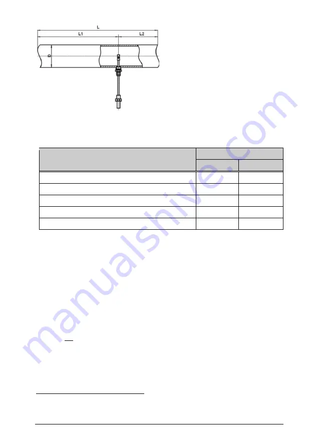
L
= Length of entire measuring distance
L1 = Length of run-in distance
L2 = Length of run-out distance
D = Inner diameter of measuring distance
Figure 2
The following Table 1 shows the required straight conduit lengths depend-
ing on the pipe inner diameter “D” and the different disturbance causes.
Flow obstacle upstream of the measuring distance
Minimum length of distance
Run-in L1
Run-out L2
Light bend (< 90°)
10 x D
5 x D
Reduction / expansion / 90° bend or T-junction
15 x D
5 x D
Two 90° bends in one plane (2-dimensional)
20 x D
5 x D
Two 90° bends (3-dimensional change in direction)
35 x D
5 x D
Shut-off valve
45 x D
5 x D
Table 1
This table lists the
minimum values
required in each case. If it is not pos-
sible to observe the specified abatement distances, increased deviations
of the measurement results are to be expected or it is necessary to take
additional measures
4
. The profile factors specified in Table 2 may become
void by the use of flow rectifiers.
Calculation of volume flow
If the cross section area of the pipe is known, the output signal of the flow
speed w
N
can be used to calculate the standard volumetric flow of the
medium. By means of a correction factor PF
5
, which depends on the pipe
diameter D the measured value can be converted to an averaged flow
velocity
N
w
which is constant over the whole pipe cross-section.
Thus, it is possible to calculate the standard volumetric flow of the medium
using the measured standard flow velocity in a pipe with known inner di-
ameter:
4
Alternatively, flow rectifiers could be used, e.g. honeycombs made of plastic or ceramics.
5
Considers the flow profile and sensor obstruction.