


4
Operating instructions
Safety-monitoring module
SRB 220XV2 V.2
EN
Opening the front cover (see Fig. 2)
• To open the front cover, insert a slotted screwdriver in the top and
bottom cover notch and gently lift it.
• When the front cover is open, the electrostatic discharge requirements
must be respected and observed.
• After setting, the front cover must be fitted back in position.
• The set drop-out delay must be entered on the front cover.
Only touch the components after electrical discharge!
U
B
Start
K1
K2
K3
K4
S31 S32 S11 S12
A1 13 23
14 24
38
Y39Y40S21 S22
S13 S14
37 47
48 A2
S33S34
SRB 220XV2
t: ………… s
U
B
Start
K1
K2
K3
K4
S31 S32 S11 S12
A1 13 23
14 24
38
Y39Y40S21 S22
S13 S14
37 47
48 A2
S33S34
SRB 220XV2
t: ………… s
Fig. 1
Fig. 2
Time setting (see Fig. 3 and 4)
• DIP switch settings:
• The DIP switches are located underneath the front cover of the
safety-monitoring module (see Fig. 3 and 4).
• Both DIP switches SW 1 (channel 1) and SW 2 (channel 2) must be
set identically.
• The DIP switches can be set when the operating voltage is on;
however, in order for the setting to be saved in the SRB 220XV2, the
voltage supply must be interrupted for approx. 3 seconds.
ON
ON
SW1
SW2
1
1
2
2
3
34
4
Fig. 3
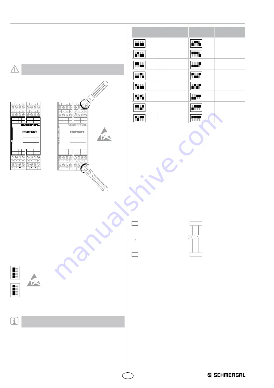
New adjustable drop-out delays and cross-wire short
monitoring for version V.2! See Fig. 4. Tolerance ± 2%
DIP switch
setting
Drop-out
delay
DIP switch
setting
Drop-out
delay
ON
1
2
3
4
<0,1 s
ON
1
2
3
4
5.0 s
ON
1
2
3
4
0.5 s
ON
1
2
3
4
8.5 s
ON
1
2
3
4
1.0 s
ON
1
2
3
4
10.0 s
ON
1
2
3
4
1.5 s
ON
1
2
3
4
12.0 s
ON
1
2
3
4
2.0 s
ON
1
2
3
4
15.0 s
ON
1
2
3
4
2.5 s
ON
1
2
3
4
20.0 s
ON
1
2
3
4
3.0 s
ON
1
2
3
4
25.0 s
ON
1
2
3
4
4.0 s
ON
1
2
3
4
30.0 s
Fig. 4
5.3 Notes
Reduction of the delay time (see Fig. 5)
• To enable a premature ending of the drop-out delay,
an NC contact must be installed at the pins Y39-Y40.
• If the feedback circuit is not required, establish a bridge.
Delayed enabling circuits (see Fig. 6)
• The drop-out delay of the safety enabling circuits 37-38 and 47-48 can
be set within the range of 0...30 seconds by means of DIP switches.
The DIP switches are located underneath the front cover of the
safety-monitoring module.
• The safety enabling circuits 37-38 and 47-48 meet STOP category 1
to EN 60204-1.
• The safety enabling circuits 13-14 and 23-24 meet STOP category 0
to EN 60204-1.
Y40
Y39
38
37
48
47
Fig. 5
Fig. 6


