


6
Operating instructions
Safety light grid
SLG 420
EN
3.4 Safety distance
The safety distance is the minimum distance between the SLG 420 and
the hazardous point, which must be observed in order to ensure that
the hazardous point can only be reached after the hazardous move-
ment has come to standstill.
The protection using individual beams must be chosen so
that bodies or body parts larger than the selected resolution
(beam di beam diameter 10 mm) of the SLG 420 are
detected.
Calculation of the safety distance to EN ISO 13855 (successor of
EN 999) and EN ISO 13857
The safety distance depends on the following elements:
• Run-on time of the machine (calculation by run-on time measurement)
• Response time of the machine and the safety light grid and the
downstream relay (entire safety guard)
• Approach speed
• Resolution of the safety light grid
Calculation of the safety distance for the multi-beam light grid:
S = (1600 mm/s * T) + 850mm
S = Safety distance [mm]
T = Total reaction time (machine run-on time, reaction time of the safety
guard, relays, etc.)
K = Approach speed 1600 mm/s
C = Safety supplement 850 mm
Example:
Reaction time of the SLG 420 = 10 ms
Run-on time of the machine T = 170 ms
S = 1600 mm/s * (170 ms + 10 ms) + 850 mm
S = 1138 mm
The following mounting heights must be observed:
Number of beams
Mounting height above reference floor in mm
2
400, 900
3
300, 700, 1100
4
300, 600, 900.1200
The formulae and calculation examples are related to the vertical set-up
(refer to drawing) of the safety light grid with regard to the hazardous
point.Please observe the applicable harmonised EN standards and
possible applicable national regulations.
The safety distance between the safety light grid and the
hazardous point must always be respected and observed.
If a person reaches the hazardous point before the hazar-
dous movement has come to standstill, he/she is exposed to
serious injuries.
Safety distance to the hazardous area
S
Hazardous point
Transmitter
Receiver
Command device
Authorised operation
Mechanical protection
Direction from which the
hazardous area is accessed
The above-mentioned formula may only be used for the vertical set-up
(refer to drawing) of the light curtain with regard to the hazard point.
The successor standards of the EN 999 for calculating the
minimum distances of the safety guards with regard to the
hazardous point are EN ISO 13855 and EN ISO 13857.
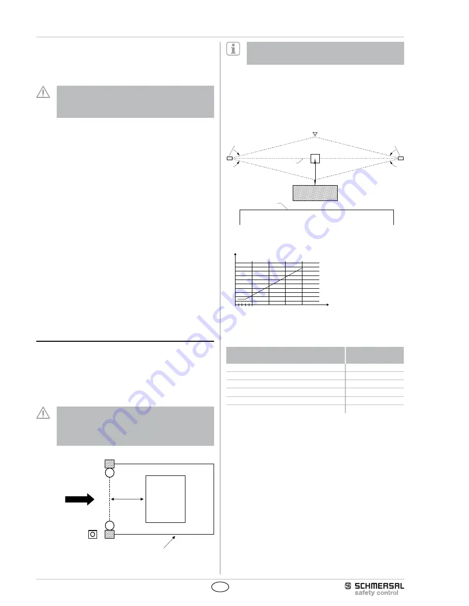
3.5 Minimum distance to reflecting surfaces
During the installation of the safety light grid, the effects of reflecting
surfaces must be taken into account. In case of an incorrect installati-
on, interruptions of the protection field could possibly not be detected,
which could lead to serious injuries. The hereafter-specified minimum
distances with regard to reflecting surfaces (metal walls, floors, ceilings
or parts) must be imperatively observed.
8°
8°
a= 262 mm
Access direction
Receiver
Obstacle
optical axis
Transmitter
reflecting body
(e.g. material container)
Limit of the hazardous point
a=130mm
5°
5°
Safety distance a to reflecting surfaces
a [mm]
D [m]
0
3 5
10
100
200
300
400
500
600
700
800
900
1000
15
20
Calculate the minimum distance to reflecting surfaces as a function of
the distance with an aperture angles of ± 2.5° degrees or use the value
from the table below
Distance between transmitter and receiver
[m]
Minimum distance
a [mm]
0.2 … 3.0
130
4
175
5
220
7
310
10
440
15
660
Formula: a = tan 2.5° x L [mm]
a = Minimum distance to reflecting surfaces
L = Distance between transmitter and receiver