10
Operating instructions
Solenoid interlock
MZM 100
MZM 100 B
EN
9. Appendix
9.1 Wiring examples
The application examples shown are suggestions They however do not release the user from carefully checking whether the switchgear and its
set-up are suitable for the individual application
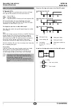
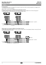
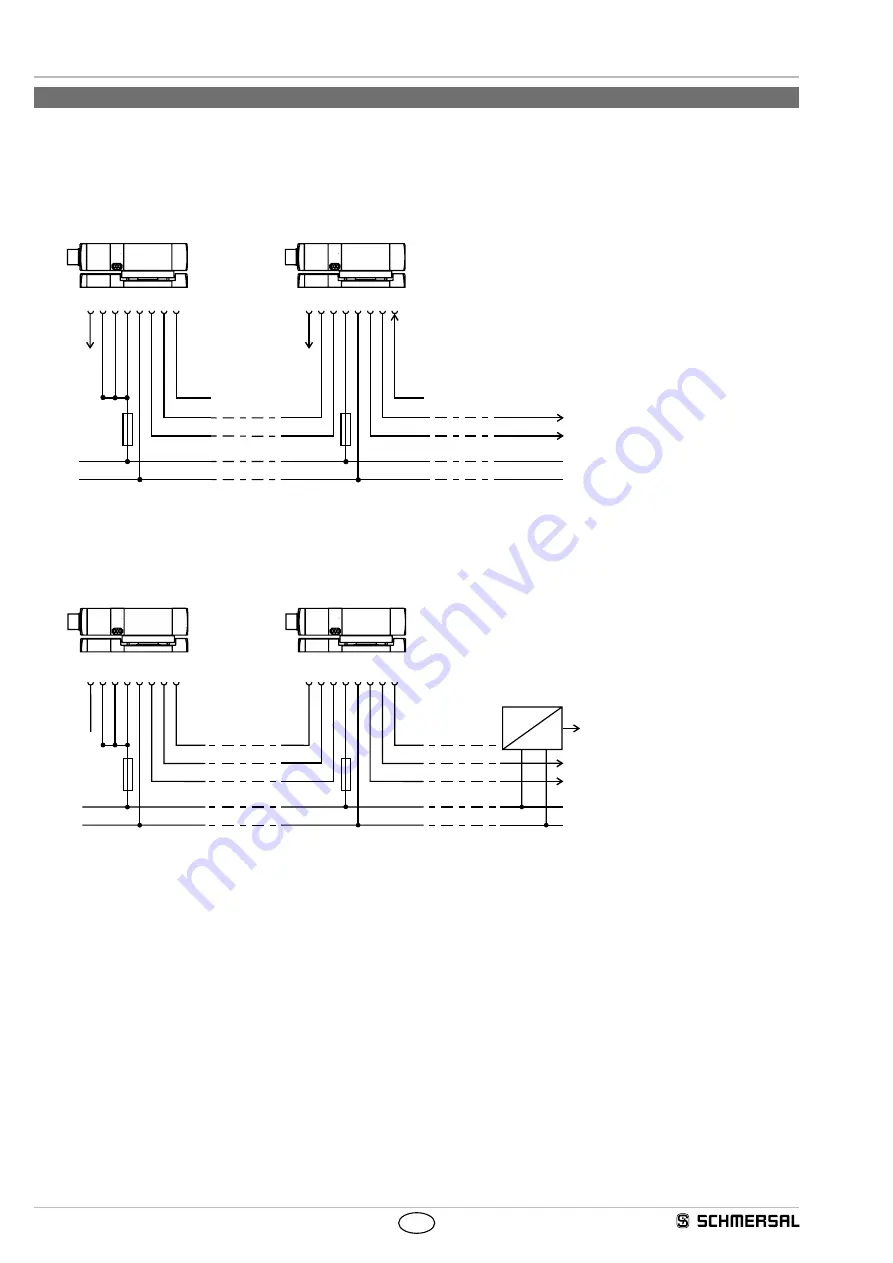
Wiring example 1: Series-wiring of the MZM 100 with conventional diagnostic output
The voltage is supplied at both safety inputs of the terminal safety component of the chain (considered from the safety-monitoring module)
The safety outputs of the first safety component are wired to the safety-monitoring module
X1
Y1
X2
Y2
1
2
3
5
6
8
X1 X2 A1 A2
Y1
Y2
1
2
3
5
6
8
X1
4
Y1
4
Y1
X2
7
Y2
7
Y2
OUT
A1 A2
OUT
SPS/PLC
IN
SPS/PLC
SPS/PLC
IN
24 VDC
GND
SPS/PLC
n-participants
Safety outputs → evaluation
Wiring example 2: series-wiring of the MZM 100 with serial diagnostic function
The safety outputs of the first safety component are wired to the safety-monitoring module The serial Diagnostic Gateway is connected to the serial
diagnostic input of the first safety component
n-participants max 31 components in series
Safety outputs → evaluation
Field bus
24 VDC
GND
1
2
3
5
4
6
8
X1
Y1
X2
SD IN
SD OUT
A1 A2
1
2
3
5
4
6
8
X1
Y1
X2
7
Y2
7
Y2
SD IN
SD OUT
A1 A2
X1
Y1
X2
Y2
SD IN
SD OUT
Y1
Y2
SD IN


