


4
Operating instructions
Safety-monitoring module
AZR 31S1
EN
5.3 Notes
Operating principle
The safety-monitoring module checks the correct position of all internal
relay contacts. During start-up, every motor generates an induced volt-
age caused by residual magnetism, which is evaluated by the safety-
monitoring module. Any interruption of the motor cable is detected and
recognised as well. To activate the AZR 31S1, the connected motor
must be standing still and the feedback input X1/X2 must be closed.
When the AZR 31S1 is connected to cable lengths > 10 m,
failures of the standstill monitor can occur.
We therefore recommend:
– short and shielded connecting cables between the safety-
monitoring module and the motor,
– lay cables to other high-capacity consumers (motors etc.)
or strong interference sources (frequency converters) at
sufficient distance and if possible not parallel to the signal
input lines (L1, L2, L3) of the safety-monitoring module.
When using frequency converters, please observe that
– the terminal stage of the frequency converter is switched off
when the motor is at standstill,
– there is no position control when the motor is at standstill.
In order to avoid any inadvertent switch-off or malfunction
(ERR-LED) of the safety-monitoring module, please ensure
that
– external influences do not trigger any movement of the
motor,
– no rotary movement of the motor can occur as soon as the
self-test is started (i.e. motor at standstill, LED's A and B
simultaneously flashing).
5.4 Application hints
Single-channel control (star contactor is not pulled-in) (Fig. 2)
• If the application does not allow for the star contactor to be pulled in
after the motor is switched off, a single-channel control of the AZR
31S1 can be realised.
• Category 1 – PL c to DIN EN ISO 13849-1
F1
A1
V2
U2
W2
U1
V1
W1
L+
L1
L–
N
K1
K2
K
A
K
B
13
K
A
T
K
B
23
L3
X1
X2
L2
L1
~ =
~ =
R
S
A2
24
14
34
33
41
PE
42
Fig. 2
R = Signal processing
S
= Monitoring
T
= Feedback circuit
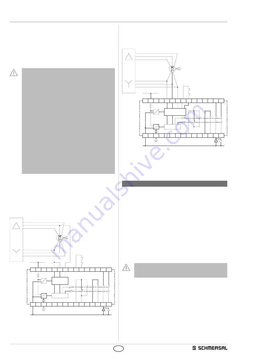
Dual-channel control (star contactor pulled-in, also when motor is
stationary) (Fig. 3)
• In case of automatic star delta start or pole changing, the star
contactor must be pulled in during the measurement process.
F1
A1
V2
U2
W2
U1
V1
W1
L+
L1
L–
N
K1
K2
K
A
K
B
13
23
L3
X1
X2
L2
L1
~ =
~ =
A2
24
14
34
33
41
PE
42
K
A
T
K
B
R
S
Fig. 3
R = Signal processing
S
= Monitoring
T
= Feedback circuit
6. Set-up and maintenance
6.1 Functional testing
The safety function of the safety-monitoring module must be tested.
The following conditions must be previously checked and met:
1. Correct fixing
2. Check the integrity of the cable entry and connections
3. Check the safety-monitoring module's enclosure for damage
4. Check the electrical function of the connected sensors and their influ-
ence on the safety-monitoring module and the downstream actuators
6.2 Maintenance
A regular visual inspection and functional test, including the following
steps, is recommended:
1. Check the correct fixing of the safety-monitoring module
2. Check the cable for damages
3. Check electrical function
The device has to be integrated into the periodic check-ups
according to the Ordinance on Industrial Safety and Health,
however at least 1 × year.
Damaged or defective components must be replaced.


