


3
AZR 31S1
Operating instructions
Safety-monitoring module
EN
Monitored inputs
Short-circuit recognition (Y/N):
No
Wire breakage detection (Y/N):
Yes
Earth leakage detection (Y/N):
Yes
Number of NO contacts:
0
Number of NC contacts:
0
Conduction resistance:
max. 40 Ω
Outputs
Number of safety contacts:
3
Number of auxiliary contacts:
1
Number of signalling outputs:
0
Switching capacity of the safety contacts:
- 13-14; 23-24; 33-34:
max. 250 V, 6 A ohmic (inductive in case
of appropriate protective wiring);
min. 10 V / 10 mA
Switching capacity of the auxiliary contacts:
41-42: 24 VDC / 2 A
Fuse rating of the safety contacts:
6.3 A slow blow
Recommended fuse for the auxiliary contacts:
2 A slow blow
Utilisation category to IEC / EN 60947-5-1:
AC-15: 230 VAC / 6 A
DC-13: 24 VDC / 6 A
Dimensions H x W x D:
73.2 mm x 45 mm x 121 mm
The data specified in this manual are applicable when the
component is operated with rated operating voltage U
e
±0%.
2.5 Safety classification
Standards:
EN ISO 13849-1, IEC 61508, EN 60947-5-1
PL:
up to e
Control category:
up to 4
DC:
99% (high)
CCF:
> 65 points
PFH value:
≤ 2.00 × 10
-8
/h
SIL:
up to 3
Service life:
20 years
The PFH value of 2.00 × 10
-8
/h applies to the combinations of contact
load (current through enabling contacts) and number of switching
cycles (n
op/y
) mentioned in the table below. At 365 operating days per
year and a 24-hours operation, this results in the below-mentioned
switching cycle times (t
cycle
) for the relay contacts.
Diverging applications upon request.
Contact load
n
op/y
t
cycle
20 %
525,600
1.0 min
40 %
210,240
2.5 min
60 %
75,087
7.0 min
80 %
30,918
17.0 min
100 %
12,223
43.0 min
3. Mounting
3.1 General mounting instructions
Mounting: snaps onto standard DIN rails to EN 60715.
Snap the bottom of the enclosure slightly tilted forwards in the DIN rail
and push down until it latches in position.
3.2 Dimensions
All measurements in mm.
Device dimensions (H/W/D): 73,2 mm x 45 mm x 121 mm
4. Electrical connection
4.1 General information for electrical connection
As far as the electrical safety is concerned, the protection
against unintentional contact of the connected and therefore
electrically interconnected apparatus and the insulation of the
feed cables must be designed for the highest voltage, which
can occur in the device.
The electrical connection may only be carried out by
authorised personnel in a de-energised condition.
Wiring examples: see appendix
To avoid EMC disturbances, the physical ambient and opera-
tional conditions at the place where the product is installed,
must meet the provisions laid down in the paragraph "Electro-
magnetic Compatibility (EMC)" of DIN EN 60204-1.
5. Operating principle and settings
5.1 LED functions
ON: Status operating voltage (LED is on,
when the operating voltage on the terminals is ON)
A: channel A (on, when frequency at channel A)
B: channel B (on, when frequency at channel B)
OUT: enabling signal (on when 13-14, 23-24, 33-34 closed)
ERR: error (on in case of malfunction)
5.2 Description of the terminals
Voltages:
A1*
A2*
+24 VDC/24 VAC / 115 VAC / 230 VAC
0 VDC/24 VAC
Outputs:
13-14
23-24
33-34
First safety enabling circuit
Second safety enabling circuit
Third safety enabling circuit
Start:
X1-X2
41-42
Feedback circuit
Auxiliary contact
* depending on the operating voltage variant
Signalling outputs must not be used in safety circuits.
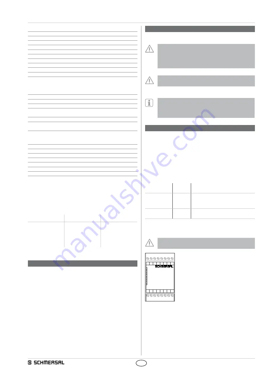
ON
A
B
OUT
ERR
A1 L1 L2 L3
A2 PE X1 X2
41 13 23 33
42 14 24 34
AZR31S1
230 VAC
Fig. 1


