30.30.01.01648/06
www.schmalz.com
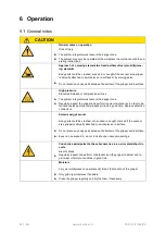
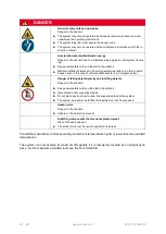
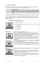
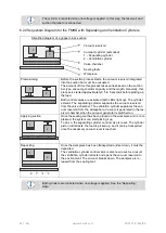
EN | 29
Electrical Connections
5.6.1 Solenoid Valves
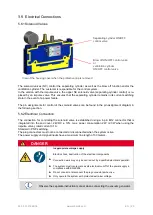
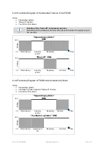
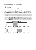
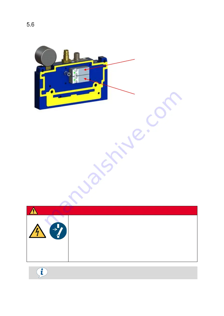
The solenoid valves (NC) control the separating cylinder as well as the blow off function and/or the
ventilation cylinder. The customer is responsible for the control system.
In the version with the impulse valve, the upper NC solenoid valve (separating cylinder control) is re-
placed by an impulse valve. This ensures that the separating cylinder remains in its current switching
state in the event of a power failure.
The pin assignments for control of the solenoid valves can be found in the pin assignment diagram in
the following section.
5.6.2 Electrical Connection
The connection for controlling the solenoid valve is established using a 4-pin M12 connector that is
integrated into the end cover. 24V DC ± 10%, max. power consumption 2 W (2.3 W when using the
impulse valve), rated current 0.1 A.
Standard = PNP switching.
The plug connectors must not be connected or disconnected when the system is live.
The power supply and signal inputs have a maximum line length of 30 meters.
DANGER
Inappropriate voltage supply
Electric shock, destruction of the electrical components
►
Connection work may only be carried out by a qualified electrical specialist.
► The system must incorporate a safe electrical cut-off of the power supply in
compliance with EN 60204.
► Do not connect or disconnect the plug connectors when live.
► Only operate the system with protected extra-low voltage.
Observe the separate instruction manual when connecting the vacuum generator.
Blow off ON/OFF control valve
or
ventilation cylinder
ON/OFF control valve
Separating cylinder ON/OFF
control valve
View of the housing cover when the protective cap is removed
(1.4)
Содержание FMHD
Страница 60: ...60 EN www schmalz com 30 30 01 01648 06 ...


