background image

2

CM5100 COMPUTER MANAGED CYLINDRICAL LOCK

HARD-WIRED (FSE/FSA) INSTALLATION MANUAL

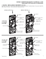
1. PREP DOOR AND FRAME:

A. Determine door hand and correct backset.

B. Mark the horizontal and vertical centerlines for the lockset, latch and strike.

C. Place template on inside of door (opposite the side that the keypad/reader will be on). Line up the correct reference lines

on the template with the edge of the door. The centerline on the door should line up with the vertical centerline of the tem-

plate.

D. Drill holes as described by template.

BEFORE YOU BEGIN:

Standard units are shipped from the factory to fit 1-3/4” doors. Verify the door thickness. If the door is not 1-3/4” thick, verify

that the door thickness option was ordered or consult factory. Hard-wired units (FSE & FSA models) will require that wiring

is brought to the door prep. In step 1, “PREP DOOR AND FRAME”, there are some suggested ways of doing this. A door

cord, electric hinge or some other form of wire transfer device will be required.

DOOR EDGE (LATCH)

FRAME (STRIKE)

DOOR FACE (LAY OUT ON INSIDE)

CM5195 ONLY

(PRIVACY FUNCTION)

CM5195 ONLY

(PRIVACY FUNCTION)

Form 51116-C

Содержание CM5100-FSA-IBO

Страница 1: ...report Manual and computer programming is supported by all models which have a keypad The PRO models are manually programmed to accept up to 100 codes Functions 5190 Office Function has Lock and Unlo...

Страница 2: ...l centerline of the tem plate D Drill holes as described by template BEFORE YOU BEGIN Standard units are shipped from the factory to fit 1 3 4 doors Verify the door thickness If the door is not 1 3 4...

Страница 3: ...d template 2 Using a 1 drill bit continue the 1 latch hole through retractor hole to a depth of 5 This will allow room for the wiring to pass around the retractor 3 Using appropriate drilling jig and...

Страница 4: ...s shown below D Using nut tool provided tighten nut onto cylinder E Line up nearest notch on nut with tab on lock washer and bend tab using nut tool so nut is secure F Install exterior gasket if used...

Страница 5: ...n threads Loctite 242 is recommended E Re install outside spindle making sure that the round end faces the handle and the spindle is positioned with its edges vertical and horizontal as shown in detai...

Страница 6: ...1 3 4 thick slide spacer over standoffs and retractor on outside escutcheon C Carefully install the outside escutcheon onto the door passing the wiring harness through the 1 hole Be sure that the pro...

Страница 7: ...the door Use socket cap screws with washers on upper standoffs and phillips head screws on lower retractor assem bly standoffs CAUTION If any fasteners such as washers fall behind the PC board remove...

Страница 8: ...DOOR FRAME REMOTE RELEASE INPUT 3 4 FROM DOOR FRAME REMOTE RELEASE INPUT 3 4 FROM DOOR FRAME REMOTE RELEASE INPUT 3 4 FROM DOOR FRAME 5 6 NOT USED PRIVACY JACK CM5193 ONLY 5 6 NOT USED 5 6 NOT USED MA...

Страница 9: ...LL INSIDE SPINDLE AND INSIDE ESCUTCHEON A Tuck main wiring harness and other wires coming from outside escutcheon under retaining clip as shown in detail B Insert inside spindle with flat side showing...

Страница 10: ...s TEKs or TouchEntry Keys TROUBLE SHOOTING PROBLEM POSSIBLE CAUSE Inside lever doesn t retract latch Inside spindle not installed Mechanical key not working Wrong cylinder cam installed or cam install...

Отзывы: