


45
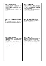
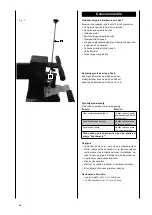
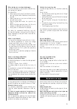
Montage des bras de commande, Fig.5
• Introduisez le bras (A) dans la tige de commande (B) et
fixez le avec le boulon 6 pans, la rondelle et l‘écrou de
sécurité. Ne serrez pas trop l’écrou afin que le bras se
laisse manipuler.
• Installez le deuxième bras de l’autre côté de la même
manière.
Montage des étriers de sécurité sur les bras de commande,
Fig. 5.1
Fixez les deux étriers de sécurité (D) à l’aide des 2 vis
cruciformes en utilisant les orifices(E) prévus à cet effet.
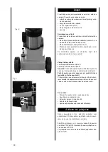
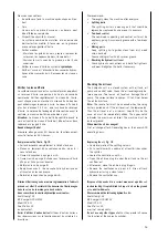
Montage du plateau de fendage, Fig. 6
Le plateau de fendage peut être positionné à 3 hauteurs
différentes selon la longueur des bûches à fendre : 55 cm,
80 cm et 103 cm.
Les vis de verrouillage de la position doivent être positi-
onnées à la hauteur désirée.
Placez le plateau à la hauteur choisie en l’introduisant
dans les supports (B). Vissez les vis de verrouillage de
position vers l’intérieur jusqu’à ce que le plateau soit par-
faitement maintenu.
Attaching the operating arms, Fig. 5
• Insert the operating arm (A) into the rocker arm (B) se-
curing it with the hex-nut (C), washer and locking nut.
The locking nut should be tightened so that the operat-
ing arm can still be moved.
• Now attach the other operating arm on the other side
according to the method described.
Attaching safety brackets on operating arms, Fig. 5.1
Attach the two safety brackets (D) with 2 recessed head
screws using the respective holes (E).
Attaching the table plate, Fig. 6
The table plate can be attached at the varying three
heights of 55 cm, 80 cm and 103 cm depending
on the length of the wood to be split. The table locking
screws A must be attached in each appropriate mounting
position.
Insert the table plate into the desired bracket B. Now
tighten the table locking screws A until the table plate
is secure.


