Schako BSK-RPR-EU Скачать руководство пользователя страница 3


Fire damper BSK-RPR-EU 


Technical documentation 


Description


Construction subject to change 


No return possible 

Version: 2021-07-01 | Page 3 


DESCRIPTION 

Fire  dampers,  installed  in  ventilation  ducts  (air  conditioning 
systems), serve for the automatic locking of fire lobbies.  
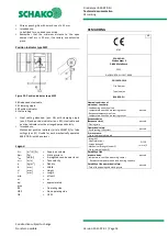
The  fire  damper  BSK-RPR-EU  corresponds  to  EN  15650,  EN 
13501-3 and EN 1366-2. 
The BSK-RPR-EU has been tested according to EN 1366-2 in com-
pliance  with  Declaration  of  Performance  no.  DoP-BSK-RPR-EU-
2017-08-09. Its classification according to EN 13501-3 is EI 120 
(v

e

 i

  

o) S. 

The  national  standards  and  guidelines  must  be  observed  in 
connection  with  this  technical  documentation,  installation, 
mounting and operating instructions.  
For functional test, service, retrofitting, etc., inspection open-
ings  must  be  provided  on  site  in  suspended  ceilings,  shaft 
walls,  connected  ventilation  ducts,  etc.,  if  necessary.  They 
must be built in in sufficient numbers and sizes and must not 
impair the functioning of the fire dampers. 
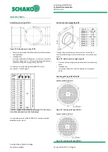
The fire dampers must be connected to the ventilation system 
by means of ventilation ducts either on one or on both sides. 
When  connected  on  one  side,  finishing  protective  gratings 
made of non-flammable building materials (EN13501-1) must 
be provided on the opposite side. 
The  fire  dampers  can  be  connected  to  non-flammable  and 
flammable ventilation ducts as well as to flexible spigots. 


Housing made of galvanised sheet steel (standard), option-
ally (at an extra charge): 


Housing made of stainless steel material no. 1.4301 
or material no. 1.4571 


Housing with DD coating (two-component top coat 
based on polyurethane varnish) inside / outside 


Model with plug-in connection (-S) or flanged connection 
(-F) according to EN 12220 and DIN 24154-1, respectively. 


Damper leaf made of silicate board, 

optionally (at an extra charge): 


DD coating (RAL 7035 / light-grey) 


Cold and hot leakage requirements according to EN 1366-
2 are complied with using circumferential rubber and intu-
mescent seals. 


Horizontal position of the damper blade axle 


The installation position is independent of the air flow di-
rection. 


Thermal trigger via fusible link 72°C; 
optionally (at an extra charge) 


equipped with electrical release devices 


Use: max. operating pressure of 1000 Pa at v

face


≤ 10 m/s


Housing leakage class C according to EN 1751 


Use  or  connection  of  a  smoke  trigger  device  with  general 
building supervisory approval (e.g. SCHAKO smoke detection 
system RMS, see technical documentation smoke detection 
system RMS) in connection with suitable electric release de-
vices  of  the  fire  damper  is  possible;  only  release  devices 
working  by  the  "currentless  closed"  principle  may  be  con-
nected  to  the  RMS  system;  the  propagation  of  fire  and 
smoke is effectively prevented. Optimal integration into the 
building  control  system  by  means  of  the  SCHAKO  EasyBus 
signalling and switching bus system (see technical documen-
tation EasyBus) or the SCHAKO fire damper mini-controller 
BKSYS (see technical documentation BKSYS).


ATTENTION 

Building systems have to be arranged, installed, changed and 
maintained in such a way that they prevent fire and propaga-
tion of fire and smoke (fire propagation) and allow evacuation 
of  people  and  animals  as  well  as  efficient  fire  extinguishing 
work.  
Smoke propagation through the air-conditioning and ventila-
tion  system  can  be  prevented  for  example  by  means  of  fire 
dampers and spring return actuators in combination with ap-
proved smoke detector devices (e.g. SCHAKO smoke detection 
system RMS). 


GENERAL 

Data and requirements according to German standards (DIN) 
must be checked on site for compatibility with current stand-
ards  and  directives  in  the  respective  states/countries  and 
adapted, if necessary. Whether the installation of flexible con-
nection pieces is required, must be determined on site. 
 

Содержание BSK-RPR-EU

Страница 1: ...1366 2 PERFORMANCE DATA For automatic locking of fire lobbies For use or connection of a smoke release device with abZ e g SCHAKO smoke detection system RMS in connection with suitable release de vic...

Страница 2: ...llation in solid walls 8 Wet installation of a fire damper complete mortar lining 8 Wet installation at a reduced distance 8 Installation information 9 Connection of ventilation ducts 9 Technical data...

Страница 3: ...a charge DD coating RAL 7035 light grey Cold and hot leakage requirements according to EN 1366 2 are complied with using circumferential rubber and intu mescent seals Horizontal position of the damper...

Страница 4: ...sible Version 2021 07 01 Page 4 MODELS AND DIMENSIONS BSK RPR EU BSK RPR EU S plug in connection Figure 1 Dimensions BSK RPR EU S BSK RPR EU F flanged connection Figure 2 Dimensions BSK RPR EU F 1 Fir...

Страница 5: ...for BSK RPR EU S Model BSK RPR EU S is delivered by default with a rubber lip seal Figure 3 Rubber lip seal Flange bores BSK RPR EU F Figure 4 Flange bores Table to DIN EN 12220 or DIN 24154 1 Nomi n...

Страница 6: ...nds BSK RPR EU F No minal size D Operating side BS Non operating side NBS L 375 500 L 375 L 500 100 98 216 x 67 Y 192 y 125 123 204 55 180 140 138 196 47 172 160 158 186 37 162 180 178 176 27 152 200...

Страница 7: ...be ex posed to direct effects of the weather and must not be stored below 20 C or above 50 C The fire damper must be protected from dirt and damage Af ter installation is complete any dirt must be rem...

Страница 8: ...hafts ducts and fire walls made of for example concrete masonry according to EN 1996 or DIN 1053 solid plaster wall boards according to EN 12859 apparent density 450 kg m and wall thick ness W 150 mm...

Страница 9: ...o on fire dampers as a result of thermal expansion in case of fire Appropriate compensation measures such as the arrangement of flexible spigots or a suit able duct routing duct angles and distortions...

Страница 10: ...00 to 250 Nominal sizes 250 to 500 Diagram 1 Pressure loss and flow generated noise without security grille Application limits max operating pressure of 1000 Pa at vface 10 m s Pressure loss and flow...

Страница 11: ...4 2 74 2 49 2 80 125 123 2 83 3 21 2 89 3 29 140 138 3 06 3 49 3 13 3 57 160 158 3 35 3 84 3 43 3 93 180 178 3 65 4 20 3 74 4 31 200 198 3 97 4 59 4 07 4 70 224 222 4 37 5 07 4 48 5 19 250 248 4 80 5...

Страница 12: ...tem type RMS Signaling and switching bus system type EasyBus 2 Fire damper mini controller BKSYS 2 Extension piece type VT RF 1 Duct connection spigot type RS 1 Security grille type ASG RF ASG RS 1 1...

Страница 13: ...ure 72 C respond Reaction of the thermal fuses inter rupts the supply voltage permanently Indication of damper end positions by integrated micro switches via potential free changeover contacts S1 S3 C...

Страница 14: ...on W 0 8 1 1 Power consumption dimensioning 4 VA Imax 8 3 A 5 ms 6 5 VA Imax 4 A 5 ms Auxiliary switch 2 x EPU Switching capacity of auxiliary switch 1 mA 3 0 5 inductive A AC 250 V Connection of supp...

Страница 15: ...Connection diagram S00 Connection diagram Spring return actuator S01 230V AC Figure 20 Connection diagram S01 The wires are colour coded and labelled Connection Cable Meaning Code No Colour Abbreviati...

Страница 16: ...ctua tor unit Pull the duct tip internal duct temperature fuse off the temperature monitoring unit and replace it with a new duct tip with internal duct temperature of 72 C ASK79 4 Reinsert temperatur...

Страница 17: ...22 250 248 280 378 315 313 355 353 400 398 450 448 500 498 190 Table 11 Length of the extension piece type VT RF as a func tion of the nominal size of the fire damper An extension piece for the BSK RP...

Страница 18: ...ir volume pst Pa Static pressure LWA dB A A weighted sound power level vstirn m s Face velocity kg m Density B mm Width H mm Height L mm Length min at least or or ap prox approximately BS Operating si...

Страница 19: ...e digits 04 LENGTH 580 or 455 S model 500 or 375 F model in mm always three digits 05 MATERIAL HOUSING SV Galvanised sheet steel V2 Stainless steel material no 1 4301 V2A V4 Stainless steel material n...

Страница 20: ...without ad dressing 32 EasyF AAC MASD 01 module mounted to BSK RPR EU incl connection to drive unit with flat cable connection with address ing 33 EasyF AAC OASD 01 module mounted to BSK RPR EU incl c...

Страница 21: ...ckness W 150 mm Product SCHAKO type BSK RPR EU Declaration of performance No DoP BSK RPR EU 2017 08 09 Dimensions Diameter mm Length L 455 580 mm S model 375 500 mm F model Unless stated otherwise the...

Страница 22: ...or design Material no 1 4301 V2A Material no 1 4571 V4A Security grille type ASG RF RS flange connection for con nection with ventilation duct connection on only one side wire or punch grille galvanis...

Страница 23: ...thus releasing the lock in the OPEN position of the locking bolt pos 44 in the trigger pos 5 Hand lever has been released and is moved toward the CLOSED position by spring force ATTENTION Do not reac...

Страница 24: ...by blocking the spring return actuator When the fusible link becomes damaged its replacement must be carried out as follows Replacement takes place by unscrewing both screws of the thermoelectric rel...

Страница 25: ...o Series Release device The following functional steps have been carried out according to the documents installation mounting and operating instructions Prior to commis sioning next functional check i...

Страница 26: ...ko de Web schako com Sample Functional check protocol for fire dampers Cons No ____________________ Defects found during the test on ________________________________________ Sluggishness due to soilin...

Страница 27: ...43 Luxembourg A 1060 Wien PL 05 500 Piaseczno Phone 352 403 157 1 Phone 352 403 157 1 Phone 43 1 890 24 62 Phone 48 22 7263570 Fax 352 403 157 66 Fax 352 403 157 66 Fax 43 1 890 24 62 50 Fax 48 22 726...

Страница 28: ...haft walls 9 Figure 12 Connection example of a ventilation duct arranged on one side and security grille 9 Figure 13 Connection example of ventilation ducts on both sides 9 Figure 14 Circuit diagram l...

Страница 29: ...ng ends BSK RPR EU F 6 Table 6 Free cross section m 11 Table 7 Weight table kg 11 Table 8 Technical data B10 B11 14 Table 9 Cable designation S00 S01 15 Table 10 Technical data S00 S01 16 Table 11 Len...

Отзывы: