background image

Document type

Document number

Rev

Page

Manual

66024

C

37 of 37

7.2

Authorisation level 1

7.2.1

Changing direction of movement

This describes how changes in direction of movement are made if the crane moves in

the opposite direction to that desired.
Example:
After installation and test operation it is found that the 3rd and 5th lever movements

operate in the opposite direction to that desired. See the example below for how to

change the 3rd and 5th lever movements.

DO AS FOLLOWS

1. Remove the battery pack. Connect the cable between the Portable Control

Unit and Central Unit and test run the crane. Then press the stop button on

the Portable Control Unit and emergency stop on the crane.

2. Twist up the stop on the Portable Control Unit and on the crane.
3. Press the Portable Control Unit's ON-button. The red LED should light

continuously.

4. Produce impulses in very quick succession with spring return switch MICRO to

RIGHT in the OFF direction until the Portable Control Unit gives a long beep

signal. Wait approx. 12 seconds until the next long beep signal then continue

with no 5 below.

Note 1. The red LED will be extinguished each time the Portable Control Unit

gives a beep signal.
Note. 2. If you do not receive the first long beep signal, start again from no 1

above and execute no 3 and no 4. quicker. No 3 above and no 4. must be

executed within max. 5 seconds.

5. Now press ON-button once.

The Portable Control Unit’s built-in beeper will give a short beep once every 5

seconds to confirm that the items above have been done correctly. If any

other beep signals are heard you must restart from item 1 again. Now you

can easily change direction, see no 6 below.

6. Now you can operate the crane. Move the 3rd control lever (which is

operating in the opposite direction to that desired) and give switch MICRO an

impulse to the LEFT in the ON direction.

The crane will now change direction and continue with the same selected

speed, in the opposite direction. Do the same with the 5th manoeuvre lever.
Move the 5th manoeuvre lever (which is operating in the opposite direction to

that which is desired) and give toggle switch MICRO an impulse to the LEFT in

the ON directionThe crane will now immediately change direction and

continue with the same selected speed in the opposite direction. If a direction

change has been made earlier for a particular lever, do the same as above

but give toggle switch MICRO an impulse to the RIGHT, in the OFF direction.
Operate and check that all crane directions go in the desired direction.

7. Press the stop button on the Portable Control Unit

Programming is now completed and the crane is operating in the directions

you decided in item 6. For radio operation, remove the cable control and test

run the crane.

If you are not satisfied with any direction/directions, repeat the above actions.

37/37

Содержание RC400

Страница 1: ...Instruction Manual RemoteControlSystemRC400 Document 66024 Revision D Language English ...

Страница 2: ......

Страница 3: ...ng welding 27 5 3 Locating the central unit 27 5 4 Mounting recommendations 28 5 5 Cable kit assembly instruction 29 6 Troubleshooting 31 6 1 General information 31 6 2 Indications from the Portable Control Unit 31 6 3 Indications on the Central Unit 33 6 4 Non functional system 35 7 Programming parameters and settings 36 7 1 General description 36 7 2 Authorisation level 1 37 All rights reserved ...

Страница 4: ...RC 400 Document number 66024 Revision C Revision date 2009 09 25 Revision history Revision Date Name Note A 2008 12 09 SCANRECO AB First creation of document B 2009 06 15 SCANRECO AB C 2009 09 25 SCANRECO AB 1 General 1 1 Terminology Abbreviation Description PCU Portable Control Unit CU Central Unit LED Light Emitting Diode DV Dump Valve 3 37 D 2014 09 08 SCANRECO AB New cover D 2014 09 08 ...

Страница 5: ...ing of the crane Due to the unlimited variety of cranes machines objects vehicles and equipment on which the remote control system are used and the numerous standards which are frequently the subject of varying interpretation it is impossible for the personnel at Scanreco to provide expert advice regarding the suitability of a given remote control for a specific application It is the responsibilit...

Страница 6: ... 1 Figure 3 1 Schematic overview of the Scanreco RC 400 General scope of delivery see your specification and Figure 3 1 No Description Qty 1 Portable Control unit PCU 1 2 Central unit CU 1 3 Battery charger 1 4 Battery cassette NiMH 7 2 VDC 2 5 Manoeuvre cable 10 meters 1 6 Emergency stop box Optional 1 7 Cable kit supply cables digital outputs 1 8 Cable kit valves cables analogue outputs 1 6 7 8 ...

Страница 7: ...rtable control unit with manoeuvre levers for proportional control and switches for ON OFF functions a central unit with connection cable for driving proportional electro hydraulic slide controllers Digitally coded control information lever deflection and switch position is sent from the control unit via electric cable or via radio to the central unit The control unit and central unit translate th...

Страница 8: ...near is available for 1 6 linear levers The manoeuvre levers and joysticks are fully proportional and have spring return to the zero position i e a dead man s handle The control units have a stop function which will immediately stop all movement All manoeuvre levers joysticks are protected with a protective frame against unintentional activation and against mechanical damage The control unit has m...

Страница 9: ...LED goes out after which it can be changed If the battery capacity is too low the control unit cannot be activated The battery capacity and operational performance is reduced in extremely cold conditions The battery is automatically charged during operation by cable control In order to reduce battery loading and for safety reasons the control unit is turned off automatically after the unit has bee...

Страница 10: ...ng the button marked twice There are 10 different radio channels to switch between by pressing this button in sequence Important notice Scanreco will introduce an automatic frequency management to the RC400 systems in end of 2009 making the above described function chapter 3 3 4 changing radio channels obsolete The automatic frequency management ensures a more reliable radio transmission highly re...

Страница 11: ...ons can be used to manoeuvre electrical hydraulic or pneumatic ON OFF functions Examples of functions Stopping and starting of the vehicle s motor throttle lever beep signal change over valves function changing for ex 7 th and 8 th function etc Make sure that you always know which digital functions that are connected for ON OFF manoeuvring Figure 3 5 Left switch panel on MAXI PCU Figure 3 6 Left s...

Страница 12: ...the switch to the right towards the rabbit will produce 100 steering once again For safety reasons a return to 100 steering can only be made if all manoeuvre levers are in their zero positions When the green LED is blinking the Micro speed function is activated The number of blinks indicates the operating speed as defined in the table below If the stop function is pressed on the controller unit th...

Страница 13: ...232 RX 5 24 VDC 3 3 8 Technical data PCU Item Technical data Battery pack 7 2 VDC Portable Control Unit effective operating time Approximately 8 hours per charge Weight MAXI Linear 1 95 2 20 kg without with battery pack Weight MAXI Joystick 1 75 2 00 kg without with battery pack Weight MINI Linear 1 45 1 70 kg without with battery pack Weight MINI Joystick 1 30 1 55 kg without with battery pack Di...

Страница 14: ...rity reversal over voltage large incoming voltage transients and EMC RF Connection of the central unit can therefore be made without risk of damage The central unit is delivered for supply voltages of 12 24 VDC 20 with negative ground There is one standard car type fuse located inside the central unit Plus fuse 10 Amp A transformer for standard mains voltages can also be used to provide the centra...

Страница 15: ... Fuse blows Proportional functions 1 8 double operating proportional functions Dump valve drive Max 2 0 Ampere short circuit proof ON OFF drive Max 1 8 Ampere short circuit proof Regulation signals Voltage or PWM Other upon request Current consumption at idle 40 mA Weight 1 20 Kg Valve and connection cables not included Dimensions WxHxD 227x205x78 mm IP Class IP65 Ambient temperature Celsius Faren...

Страница 16: ...5 of 37 3 5 Valve and connection cables There are several connection cables depending on the valves and the extra functions used In Figure 3 8 an example of a cable kit to Danfoss valves is shown Figure 3 8 An example of a cable kit to Danfoss valves 15 37 ...

Страница 17: ...rd Central Units type 2000 Danfoss and type 3000 PWM Important notice If a central unit is delivered without pre mounted cables the installer is strongly advised to follow the instructions given in chapter 5 5 in this manual pages 27 and 28 Installation instructions Cable kit assembly instruction K7 DV K4 EX1 K6 EX2 K1 Analog outputs 1 4 K3 Analog outputs 5 8 16 37 ...

Страница 18: ...1 11 GND K3 11 GND K1 12 3 Fault monitor K3 12 7 Fault monitor K1 13 Danfoss module supply K3 13 Danfoss module supply K1 14 Danfoss regulated supply K3 14 Danfoss regulated supply K1 15 GND K3 15 GND K1 16 4 Fault monitor K3 16 8 Fault monitor K4 EX1 Digital outputs inputs K6 EX2 Digital outputs inputs Pin no Description Pin no Description K4 1 Digital output 1 K6 1 On Signal K4 2 Digital output ...

Страница 19: ...GND K3 14 8A GND K1 15 PWM K3 15 PWM K1 16 4B GND K3 16 8B GND K4 EX1 Digital outputs inputs K6 EX2 Digital outputs inputs Pin no Description Pin no Description K4 1 Digital output 1 K6 1 On Signal K4 2 Digital output 2 K6 2 Digital output 7 K4 3 Digital output 3 K6 3 Digital output 8 K4 4 Digital output 4 K6 4 Digital output 9 K4 5 Digital output 5 K6 5 GND K4 6 Digital output 6 K6 6 Digital outp...

Страница 20: ...emote control system is disconnected The crane stop function must be suitably located and easily accessible Before operation is started the driver must inform all fellow workers about the stop function and its location Crane stop function box is not a scope of delivery from Scanreco it is the installers responsibility With the central unit switch in MANUAL position and an electric dump valve the s...

Страница 21: ...l unit The battery must be used until the LED goes out after which it can be changed If the battery capacity is too low the control unit cannot be activated The battery capacity and operational performance is reduced in extremely cold conditions The battery is automatically charged during operation by cable control In order to reduce battery loading and for safety reasons the control unit is turne...

Страница 22: ...24 C 21 of 37 3 7 1 Technical data Battery Item Technical data Type 6 Cell NiMH battery Nominal voltage 7 2 VDC Weight 0 20 kg Dimensions WxHxD 150x50x28 mm IP Class IP65 Ambient temperature Celsius Farenheit 0 C to 45 C approx 32 F to to 115 F 21 37 ...

Страница 23: ...tallation The battery charger must be mounted in a vibration free area inside the cab or indoors and be protected against damp direct sunlight and temperature variations Operating ambient temperature is 0 C to 70 C but could be narrower depending on the battery specification The supply voltage to the battery charger should be 10 VDC to 35 VDC externally fused with 3 0 Amp fuse The batter charger i...

Страница 24: ...e continuously ON There are two LED indicators on the battery charger Red LED power Indicates supply power Green LED charging status is blinking Battery is charging the charger is in fast charge mode Green LED charging status is continuously ON Battery is charged the charger is in trickle charge mode 3 8 4 Battery charging via cable control If the operator is using the cable control facility and t...

Страница 25: ...10 VDC to 30 VDC Fuse Not included Use only with 3 A external fuse Battery charger current consumption without battery pack 10 20 mA Battery charger current consumption with battery pack 130 140 mA Weight 0 25 kg Dimensions WxHxD 252x85x36 mm IP Class IP21 Ambient temperature Celsius Farenheit 0 C to 70 C approx 32 F to to 160 F 24 37 ...

Страница 26: ...isited During operation walk or stand at a suitable distance from the crane to be able to get a good view of the operation No unauthorised persons may be within the crane s working area Be aware that it is forbidden to convey loads over himself or fellow workers Release all manoeuvre levers dead man s handles if crane movement control is lost and then immediately press the stop function on the con...

Страница 27: ...y stop switches on the crane and on the control unit 4 Cable operation Connect the control cable between the control unit and the central unit crane 5 Radio operation Place a newly charged battery in the control unit s battery holder 6 Press and the red LED will light continuously 7 The system is now ready for operation The driver must be aware of all manoeuvre lever joystick and switch functions ...

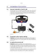
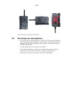
Страница 28: ...ways be disconnected from other equipment i e power supply cables and all valve contacts the EX cables contact must be disconnected 5 3 Locating the central unit Important The central unit must be mounted in accordance with the recommendations given below see figure 5 2 To ensure the longest possible life for the central unit and its cables the central unit must always be mounted so that the valve...

Страница 29: ...s high and free as possible An antenna screened and surrounded by fixed objects will considerably impair radio reception An external antenna is available upon request The antenna pin must not touch any metal object The central unit should be mounted in a vibration free location and not be subjected to strong sources of heat for example exhaust pipes etc Supply and valve cables should be mounted fa...

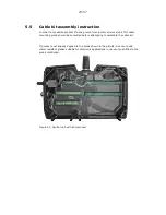
Страница 30: ...voluntary service stops this cable mounting guide should be consulted before attempting to assemble the cable kit If grease is not already applied to the areas shown in the picture be sure to add water resistant grease suitable for electronic applications in relevant quantities to the areas mentioned Figure 5 3 Central unit with lid removed 29 37 ...

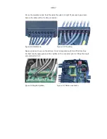
Страница 31: ...al Secure the cable with a tie strap or similar Figure 5 4 Membrane Figure 5 5 Tie strap Apply grease as shown on the picture Cover all exposed metal and fill all cavities For best result apply grease in the cavities on the connector prior to fitting the single wire connectors to it Figure 5 6 Applied grease Figure 5 7 Cable orientation 30 37 ...

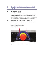
Страница 32: ... contacted Always check the Type and Serial number on the related systems Portable Control Unit and Central Unit before distributor or Scanreco AB Sweden is contacted 6 2 Indications from the Portable Control Unit Status and alarm indications can be read from the Portable Control Units LED MICRO and LED ON and also via built in buzzer see figure 6 1 1 Left hand side of stop button LED MICRO 2 Righ...

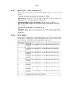
Страница 33: ...ion 6 2 2 Error codes During start up of the Portable Central Unit a self test is conducted any errors found are presented by an error code using ON LED and buzzer flashing alarming a certain amount of times the number of times represents a certain error Indications Meaning 1 Lever Joystick at position 1 not in neutral position at start up or defective 2 Lever Joystick at position 2 not in neutral...

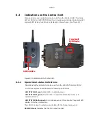
Страница 34: ... 3 1 Operational status indications Operational status indications can be read from the LED STATUS and LED DV A functional system should indicate the following on LED ON LED STATUS lit red Central Unit is in standby mode LED STATUS lit green Central Unit is in operational standby mode or in operational mode LED STATUS flashing red Error code sequence Check double 7 segment LED display for further ...

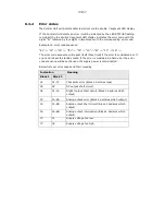
Страница 35: ... will repeat itself three times if the error is considered a soft error and reboot to standby mode if the error is considered a hard error the error code sequence will be continued until supply power is disconnected Below list over error codes and their meaning Indication Block 1 Block 2 Meaning 01 01 07 Checksum error Block 2 declares type 02 02 DV output short circuit 04 01 14 Digital output sho...

Страница 36: ...m operate via cable control function Does the system work manually i e with the system in MANUAL mode Place switch into REMOTE position check and verify how the Central Units LEDs and double 7 segment LED display indicate Activate Portable Control Unit check and verify how the Portable Control Units LEDs and buzzer indicate Activate each available function one at a time check and verify how the Ce...

Страница 37: ... in the simplest way all programming calibration of manoeuvre characteristics is made during operation so called on line All programming calibration are made from the portable control unit Programming is simple and does not require tools instruments The control system is furnished with and prepared for 2 way duplex communications and for signal handling of functions such as ramp parallel lock dead...

Страница 38: ...3 above and no 4 must be executed within max 5 seconds 5 Now press ON button once The Portable Control Unit s built in beeper will give a short beep once every 5 seconds to confirm that the items above have been done correctly If any other beep signals are heard you must restart from item 1 again Now you can easily change direction see no 6 below 6 Now you can operate the crane Move the 3rd contro...

Страница 39: ......

Страница 40: ......

Отзывы: