


hurry
SCAN
®
10, digital, 1064 nm, f = 254 mm
Rev. 2.6 e
2 The hurrySCAN
®
10 – Principle of Operation
8
innovators for industry
Position Signals, Image Field and X-Y
Reference System
Position signals are digitally transferred from the
controller to the scan head.
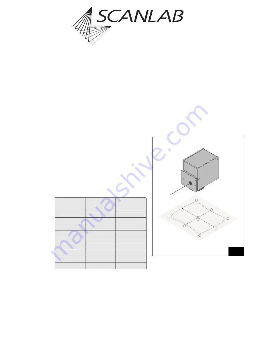
Figure 4
shows the definition of the X-Y reference
system which is used for the position signals trans-
mitted to the scan head. The orientation of the axes
corresponds to the orientation used by the RTC
®
boards from SCANLAB: The Y axis points in the oppo-
site direction of the entry beam (and the Z axis in the
opposite direction of the exit beam). Consequently:
Scanner 1 deflects the beam in the Y direction,
Scanner 2 in the X direction.
The scan head is calibrated in such a way that for a
scan angle of 0.408 rad optically with excursion in
the negative axis direction the bit-value "1311" has to
be transmitted, for the neutral position (null point)
the bit-value "32768, and for a scan angle of
0.408 rad optically with excursion in the positive axis
direction the bit-value "64225".
The maximum adjustable scan angle is (1 / 0.96)
larger than the calibration angle. The input signal
values for the maximum adjustable image field points
(see
figure 4
) are listed in the following table.
Vignetting can occur at a particular scan angle
dependent on the specific scan head and objective.
The laser beam is then partially blocked within the
scan head or objective, which results in transmission
losses. The higher the power loss, the greater is the
risk of damage to the scan system. In view of this, the
technical specifications
page 34
include not only the
calibration angle, but also the maximum allowed
scan angle. This is not the same as the maximum
adjustable scan angle. To avoid scan system damage,
make sure the maximum allowed scan angle is never
exceeded.
The maximum allowed scan angle is derived from the
geometric and optical data of the employed compo-
nents (see the
section "Customized Optical Configu-
ration" on page 6
). In some cases, particularly with
sufficiently small calibration angles, the maximum
allowed scan angle can be larger than the maximum
adjustable angle. In such cases, the specified
maximum allowed scan angle has no practical rele-
vance.
Figure 4
also depicts the pillow-barrel-shaped distor-
tion of the square image field and shows the orienta-
tion of this distortion with reference to the axes. The
field distortion is caused by the beam path within the
scan head and by the characteristics of the objective.
It must be compensated by the controller.
If you use a SCANLAB RTC
®
interface board or an
RTC
®
SCAN
alone standalone board for controlling
the scan head, the field distortion is compensated
automatically. Before data values are transferred to
the scan head, the values are transformed by the
RTC
®
boards with the help of a correction table. A
Position
X bit-Value
(CHAN2)
Y bit-Value
(CHAN1)
0
32768
32768
1
65535
32768
2
65535
65535
3
32768
65535
4
0
65535
5
0
32768
6
0
0
7
32768
0
8
65535
0
4
Positions in the image field
X
Y
1
8
7
6
5
4
3
2
0