background image

Table of Contents 

1


Introduction


1


1.1


Style


Conventions


1


1.2


Required


Tools


&


Supplies


1


1.3


Required


Parts


for


Completion


2


1.4


Included


Parts


Description


3


2


Assembly


Instructions


4


2.1


Parts


Sheet


Removal


4


2.2


Cutting


Control


Surface


Bevels


5


2.3


Horizontal


Component


Assembly


6


2.4


Vertical


Component


Assembly


8


2.5


Landing


Gear


Assembly


9


2.6


Servo


EZ


Connector


Assembly


&


Installation


12


2.7


Wing


Servo


Installation


13


2.8


Upper


Vertical


Fuselage


Installation


14


2.9


Electronics


Installation


15


2.10


Gusset


Installation


18


2.11


Painting/Decorating


19


3


Setup


and


Tuning


20


3.1


Center


of


Gravity


20


3.2


Radio


Setup


and


Mixing


20


3.3


Control


Throws


and


Expo


21


3.4


Launching/Take

Off


21


3.5


Flying


Tips


21


3.6


Repairs


&


Spare


Parts


22

Содержание Cherokee 24

Страница 1: ...m Wingspan 24 ESC 10A Brushless Overall Length 18 3 Motor 40 to 50 watt out runner 14g Wing Area 133 9 in2 Servo 4x 3 6g Sub Micro Flying Weight 3 9oz 111g RX 6 Channel 4 ch minimum Intended Use Indoor Outdoor Battery 180 to 300mAh 2S 7 4V 25C LiPo or similar Revised 2016 10 19 ...

Страница 2: ...ossible for you to experience a wide performance envelope This means that no matter how you like to fly you ll enjoy both stability and maneuverability without any sacrifice in precision or control feel Your Sawn Craft Cherokee 24 aircraft kit represents the benchmark of indoor flight performance and aerobatic versatility All you have to do next is read and apply the information presented in this ...

Страница 3: ...onent Assembly 6 2 4 Vertical Component Assembly 8 2 5 Landing Gear Assembly 9 2 6 Servo EZ Connector Assembly Installation 12 2 7 Wing Servo Installation 13 2 8 Upper Vertical Fuselage Installation 14 2 9 Electronics Installation 15 2 10 Gusset Installation 18 2 11 Painting Decorating 19 3 Setupand Tuning 20 3 1 Center of Gravity 20 3 2 Radio Setup and Mixing 20 3 3 Control Throws and Expo 21 3 4...

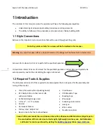
Страница 4: ...the specified operation Circled items will typically be accompanied by text further identifying the region of interest 1 2 Required Tools Supplies The list below contains all of the required tools and supplies that are required for the assembly and tuning of this model Clean flat work surface building board 11 hobby knife or other razor knife with spare blades 2x Metal straight edge ruler T Pins 1...

Страница 5: ... ensure the nicest looking finished product the following products are offered on Sawn Craft com See the Building Supplies tab for these products 2 The order of assembly presented in this instruction has been tested and it is recommended that you do not differ from them to provide the most accurate and easiest assembly possible Also the construction techniques of many of our aircraft are extremely...

Страница 6: ...Motor Spacers c Rudder d Elevator e Wing 2 each f Aileron 2 each g 3mm EPP Gussets 2 each long 2 each short h Lower Vertical Fuselage i Horizontal Fuselage j Upper Vertical Fuselage k Small Parts Bag Pictured at right k 1 25mm Wheel 3 each k 6 Plywood Motor Mount k 2 8 5 Carbon Strip k 7 Plywood Control Horns 4 each k 3 5 Carbon Rod 2 each k 8 Wire Control Rods 4 each k 4 5 5 Carbon Rod k 9 Micro ...

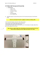
Страница 7: ...t of the sheet you may choose to clean up the remaining tab on the foam pieces with a hobby knife and some sandpaper 2 Find and mark with masking tape the bottom of the horizontal fuselage bottom of the wing halves bottom of the ailerons and bottom of the elevator The bottom of these components will have a slot milled for carbon strips Find and mark with masking tape the LEFT side of the rudder an...

Страница 8: ... the foam with the single edge razor blade held against both rulers Angling the blade makes a smoother cut Both ailerons will be beveled on their leading edges ensuring that they are mirror images of each other The rudder will be beveled on its leading edge but the bevel should be cut out of the right side of the part Place the rudder with its left side down on the table and cut the bevel from the...

Страница 9: ...rom gluing the model to the building surface Pin the horizontal fuselage component to the building surface Glue in the 8 5 carbon strip elevator spar into the elevator Glue the wing halves in place Wipe off excess glue Run a bead of glue along the spar slot and press the 22 75 carbon strip spar into place Wipe off any glue that has squeezed out of the slot Wipe off all glue outside of foam joints ...

Страница 10: ...aces gently touching ensuring that the parts are centered or otherwise aligned correctly depending on the surface Run the smallest possible bead of foam glue along each seam Run a finger along each seam to push the glue between the mating parts Blot up excess glue with a paper towel Let dry at sufficiently for the glue to fully cure Leaving the parts overnight is ideal for the strongest and most t...

Страница 11: ...uring that all of the front of the pieces line up Apply glue into the control horn slots in the elevator and ailerons and insert the control horns all the way so that the bottom of the horn touches the table 8 3 While the glue is curing on that part take your chosen motor and mount it to the plywood firewall using the screws that came with your servos Next using the included 3mm and 6mm motor spac...

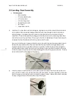
Страница 12: ...d hubs to go easily onto the axle Tape one end of the axle in place and bind the other side with the black thread provided in the kit Remove the tape and bind the other side Note that the axle should be arranged between the angled components to be as parallel to the spar as possible to that the plane rolls as straight as possible when taxiing Adjust the axle for even overhang on each side and for ...

Страница 13: ...Craft Cherokee 24 Manual 10 17 16 10 3 Bend the 3 5 1 16 steel rod according to the figure below Note that this diagram when printed in booklet form as included in your kit should be very close to 1 1 scale ...

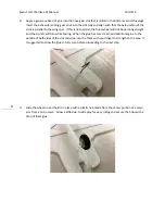
Страница 14: ...l not be pointing straight and the aircraft will turn while taxiing When the glue has cured a bit add additional glue to the outside of both sides of the slot and wipe into the foam with your finger to strengthen the area It is suggested to allow the glue to fully cure before proceeding to the next step 5 Slide the wheel on and hold it in place with a plastic hub made from the center portion of a ...

Страница 15: ...low The correct order of components for all servos when assembled is from the top of the servo Screw Connector Servo Horn Disk For more control surface throw you will want to use the furthest hole on the servo horn from the servo You may need to open the hole in the servo horn to allow the EZ connector to pass through 12 2 Install the servo horns onto the servos and secure with the included screws...

Страница 16: ...as close to perfectly straight in the front back direction as possible 13 2 Once the glue has cured run the wire from the right aileron servo through the hole in the lower vertical fuselage 3 Install the Z bend end of each control rod into the hole in the control horn Gently deflect the ailerons toward the top of the airframe and insert the straight end of the control rod into the hole that is in ...

Страница 17: ... place and hold in position with T pins until the glue dries Apply a bead of glue to the rudder hinge below the elevator Wipe off excess glue to save weight 14 6 Glue the firewall and spacer assembly to the front of the airframe making sure that you use sufficient glue to create a strong bond as this is a high stress area Try to keep glue out of the hole in the assembly as the motor shaft will nee...

Страница 18: ...ed a Y cable to drive the ailerons from one receiver channel If you install a six channel receiver a Y cable is not needed as the aileron servos can plug directly in to AIL and AUX channels on the receiver and are mixed in the transmitter 2 If your rudder and elevator servos fit in the pre cut slots great If they are larger carefully trim away a little foam with a sharp hobby knife We want a snug ...

Страница 19: ...e sure you locate it so the plugs are accessible 4 Solder the ESC and motor wires together and add the correct battery connector to the ESC ensuring that the motor spins in the correct direction Once all of the connections are made attach the motor to the firewall such that the wires point down and to the left side of the plane Run the ESC radio connector wire to the receiver by passing it through...

Страница 20: ...pair of same size boxes 17 5 Attach a strip of the opposite side of Velcro hook and loop tape to the underside of the horizontal fuselage component than you use on your batteries Make it longer that the battery to allow fine adjustment to the plane s center of gravity Attach the opposing hook and loop tape to battery packs to hold them in place when in use ...

Страница 21: ...e elevator hinge You also will notice that your rudder servo horn doesn t clear the gusset You will need to cut an approximately 1 long by 5 tall window in the gusset for the horn to clear fully Once satisfied with the fit use foam glue and t pins to secure the gusset until the glue is cured You can now connect the rudder control rod to the servo You will want to bend the control rod as shown in t...

Страница 22: ...ater based paints have been used with success in the past as have permanent markers Prior to using any paints or markers test on a scrap piece of foam to ensure that it doesn t damage the foam Remember that any weight you add to the airframe will affect its performance so keep heavy applications of paint and decals to a minimum You would be surprised at how quickly the weight from paint adds up Ou...

Страница 23: ...dio Setup Mixing Depending on the transmitter and receiver that you are using to control your model you may find that you need to do some special setup to make the control surfaces work properly Aircraft Setup Reference Transmitter Wing Mode Mix 1 Mix 2 Notes Spektrum DX6i DualAile N A N A Differential 12 if desired Spektrum DX7s DX8 Dual Aileron N A N A Differential 12 if desired Spektrum DX6 DX7...

Страница 24: ...offs are possible on smooth surfaces Advance the throttle and allow the model to gain enough speed to fly before trying to use the elevator to pitch up as premature elevator application may push the tail skid down onto the ground preventing take off 21 3 5 Flying Tips This aircraft is designed to fly in the space as small as a single basketball court Being so light weight it is recommended that th...

Страница 25: ...weight it is surprisingly durable If a part of the model is damaged it can typically be repaired using small pieces of 3M Blenderm tape or by gluing using Beacon Foam Tac If a part is damaged beyond repair simply send us an email at Support Sawn Craft com as we have replacement parts for purchase 22 ...

Отзывы: